Submarines Class Type Balilla

The Balilla class, consisting of four units dedicated to as many patriots, was the first class of submarines to be built in Italy after the end of World War I, after a “pause” of a few years due to the difficult Italian economic situation after the conflict. In the first half of the 1920s, with the gradual improvement of the Italian economy, the Regia Marina decided to launch a plan to renew the submarine fleet, starting with the construction of a class of large displacement submarines capable of operating outside the Mediterranean for long periods. The intent was to carry out an offensive against enemy traffic even in faraway oceans controlled by the adversary (according to some sources, the Balilla were designed for the war against traffic in the Indian Ocean, departing from Italian bases in East Africa).

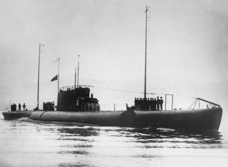
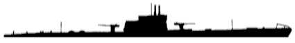
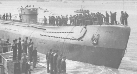
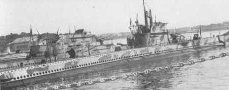
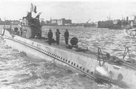
Balilla in the early years of service with the radio masts raised

Thus was born the Balilla class, whose construction was ordered with the 1923-1924 naval budget (the first in which the Navy began to receive the necessary funding for the renewal of the fleet after the end of the Great War) and entrusted to the Ansaldo San Giorgio del Muggiano shipyards, which in 1925, the year of their establishment (for another source,  in 1927), changed their name to Odero Terni Orlando.

Grand Admiral Paolo Thaon di Revel, appointed Minister of the Navy on October 31st, 1922, had decided that the renewal of the submarine fleet should begin with the construction of “prototypes” of new classes of submarines, some of which should also be able to operate in the oceans. At the end of 1922, the development of the design of these prototypes was entrusted to the ‘Ship Design Committee’, and then passed to other boards. A board composed of the Deputy Chief of Staff of the Navy, the directors general of the Ministry of the Navy, the head of the Submarine Department of the General Staff and the commander of the Submarine Squadron of La Spezia was charged with studying whether it would be more convenient to build four large cruise submarines or five medium cruise submarines; the decision, unanimously, was for the first option, according to the reasoning that such boats, being also usable in the oceans, would be useful in the event of war against certain countries, starting with France.

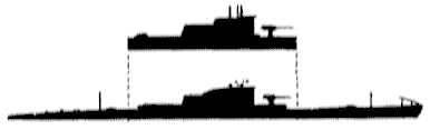
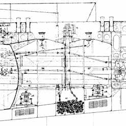
The General Staff of the Navy established some fundamental characteristics that the new boats should have such as: operational depth of 100 meters, torpedo armament of the caliber of 533 mm, artillery armament with both anti-ship and anti-aircraft functions, speeds of 17 knots on the surface and 8 knots submerged. Inspired by the German “submarine cruisers” of the Great War, the Balilla belonged to the “double total hull” type with an internal hull, tested to withstand a depth of 100 meters, formed by a cylindrical spindle that formed two truncated cones at the ends, with the emergence, rapid and trim boxes and lubricant tanks inside, and an outer hull, formed by a lightweight structure which included the floodable compartments (which surrounded most of the resistant hull) and the open spaces. The fuel was partly contained in the inner hull and partly in the double bottoms. Developed privately by the Ansaldo San Giorgio shipyards in collaboration with the technical departments of two other large shipbuilding companies, the Odero Terni Orlando and the Cantieri Riuniti dell’Adriatico, the total double hull would become one of the three main types of submarines built for the Regia Marina in the interwar period, together with the “single hull with counterhulls and double external bottoms” type designed by Colonel Curio Bernardis of the Naval Engineers and the “double hull” type partial hull” designed by Lieutenant Colonel Virginio Cavallini of the Naval Engineers.

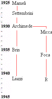
With a displacement of 1,464 tons (some sources indicate 1,450) on the surface and 1,927 (other sources indicate 1,904) submerged and an overall length of 86.75 meters, the Balilla were the largest submarines ever built in Italy, and even later they were surpassed in size by very few classes. Those were, among the “attack” ocean submarines, the unsuccessful Ettore Fieramosca of 1931,  1,556/1,965 tons, the three Calvi class 1,550/2,060 tons in 1935 and the four Admirals class 1941, with a displacement of 1,702/2,184 tons. In addition, the large minelaying submarine Pietro Micca of 1,567/1,967 tons of 1935 and the transport submarines class R, of 2,210/2,606 tons, completed starting from 1943.
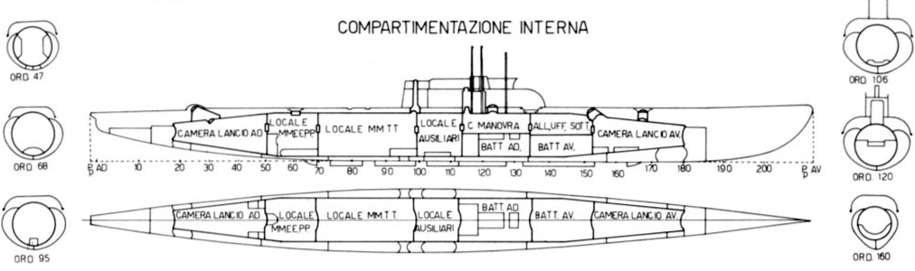
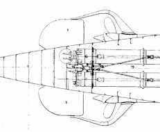
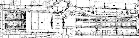
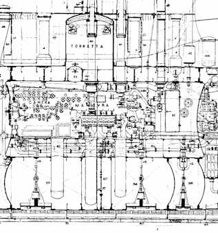
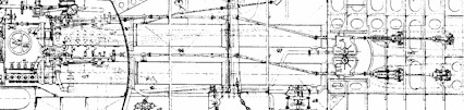
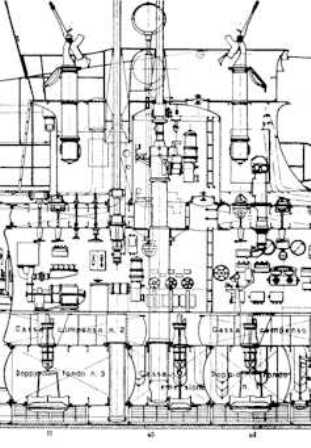
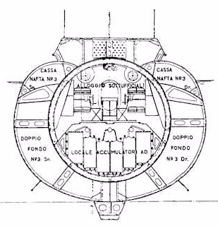
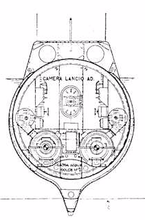
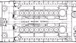
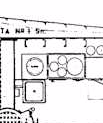
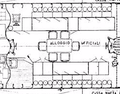
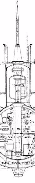
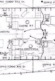
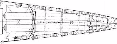
Internal layout

The submarine Balilla belonged fully to the category of “cruiser submarines” of large size and great autonomy (the first Italian units of this kind: they were, in fact, the first real ocean-going submarines of the Regia Marina), designed for the war against merchant traffic in distant seas, with long missions that would have taken them a great distance from their bases of departure. Their design, developed in 1923 by the Ansaldo-San Giorgio company, had been influenced by that of the German UE II class (displacement of 1,164 miles on the surface and 1,512 submerged, range of 11,470 miles at 8 knots), one of which, the U 120, had been delivered to Italy in November 1918. Given their intended use, great importance was given to autonomy, nautical qualities, and habitability in their design.

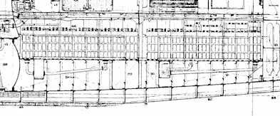
The resistant hull of the Balilla was divided into seven watertight compartments. From bow to stern they were: forward torpedo launch chamber, officers’ and non-commissioned officers’ saloon and bow battery room, control chamber and stern battery, auxiliary engine room, diesel engine room, electric propulsion engine room, aft torpedo launch chamber. A total of 456 tons of water could be loaded into the ballast tanks. Compressed air for the tank of the ‘rapid’ was stored in containers with a total capacity of 11,900 litres, and its use had to be limited to emergency cases only, as the recharging of the compressed air, carried out with San Giorgio electric compressors, required a long period on the surface.

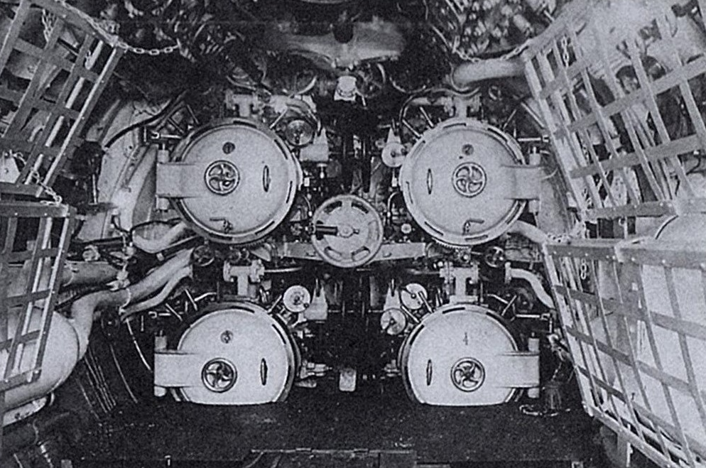
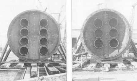
The forward torpedo room

The steering rudder had an area of 7.4 square meters. The forward planes, located above the waterline, were foldable, while the aft ones were located just aft of the propellers. The planes were electrically operated from the control chamber, but in case of emergency they could also be operated manually from the forward torpedo launch chamber (for bow depth planes) or from the aft torpedo launch chamber (for stern planes).

Officers and non-commissioned officers were accommodated in two adjacent cabins, located above the forward battery room. Sailors slept in bunk bunks in the two launch chambers.

The supply of fresh water, stored in three tanks, was 12 cubic meters. If necessary, an additional eleven cubic metres could be stowed in the compensation boxes. There was also an electric distiller on board capable of producing 2,000 litres of fresh water per day. For fresh food there was a cold room of the Audiffen Singrun type. There were two galleys, an electric one located in the forward launch chamber, and a diesel one, usable only in surfacing, inside the conning tower.

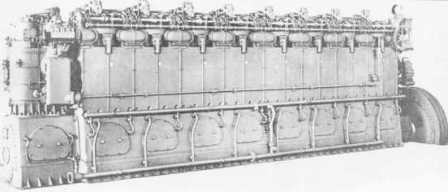
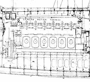
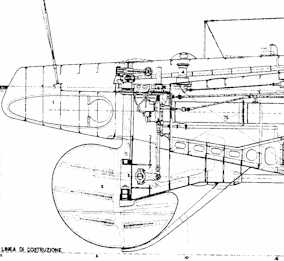
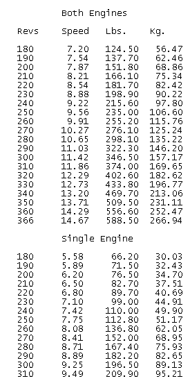
The propulsion system for surface navigation consisted of two FIAT Q 458 two-stroke diesel engines with a total power of 4,900 hp (2,450 hp per engine; for another source 4,000 hp in total, 2,944 kW), at 380 rpm, which allowed a maximum speed of 17.5 knots. The one for submerged navigation was represented by two Savigliano direct current electric motors with a total power of 2,200 hp (1,620 kW in total; 1,100 hp for the engine at 280 rpm for one hour, or 600 for the engine at 230 rpm for 3 hours), with a maximum speed of 8.9 knots. There were two, three-bladed propellers.

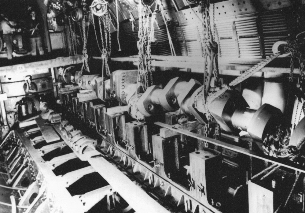
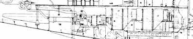
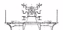
Installation of one of the main engine shafts

(According to another source, however, the speeds of 17.5 knots on the surface and 8.9 in submerged were the maximum speeds envisaged by the project, while the actual ones were slightly lower: 16 knots on the surface – 17.5 knots were reached only in the tests – and 7 submerged).

With a supply of 152 tons of diesel, the surface range was 3,000 miles at 16 (or 17) knots, 7,050 at 8.5 knots and 12,000 (or 13,000) at 7 knots. Submerged range was 110 miles at 3 knots, 80 miles at 4 knots and 8 miles at 8.9 knots. The electric motors were powered by a bank of lead-acid batteries, consisting of 240 elements divided into four groups of 60. Each accumulator could generate 3,200 ampere-hours for one hour, or 6,300 ampere-hours for 10 hours.

There was also an auxiliary engine (consisting of a FIAT Q 304 diesel generator, derived, according to one source, from the German MAN diesel engines of the Great War) with 425 or 500 hp (368 kW) and 500 rpm for surface navigation (it supplied energy to the two main electric motors and it was also used to charge the batteries and to supply electricity for auxiliary services),  with which it was possible to reach a maximum speed of 7 knots and a range, at this speed, of 12,000 miles.

The testing depth was 100 meters (110 for another source; during the tests the Millelire reached 122 or 135 meters), considerable for the twenties.

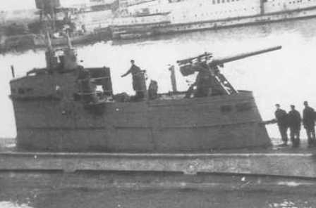
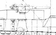
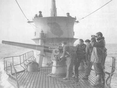
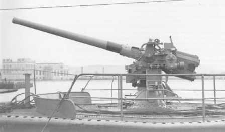
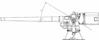
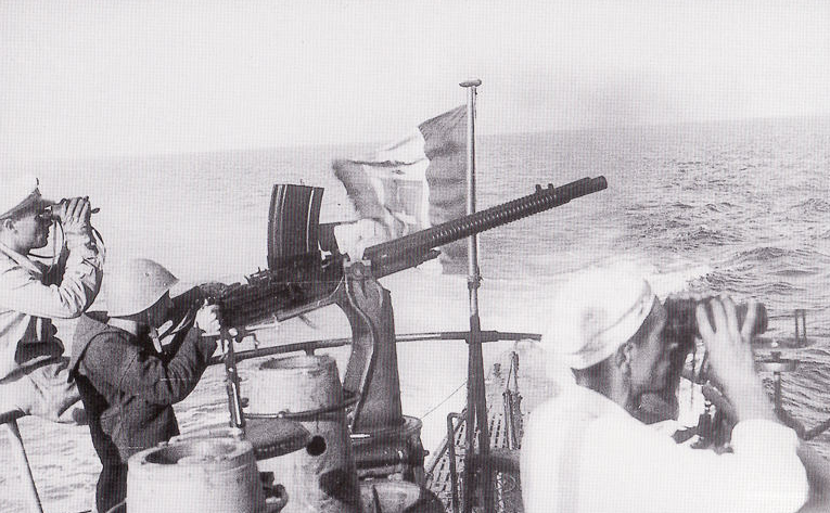
The armament originally consisted of a 120/27 mm OTO Mod. 1924 (with a reserve of 150 rounds), placed in an unusual shielded housing forward of the conning tower (of which this housing was a continuation, forming a single block with it), and two single 13.2/76 mm machine guns (with a reserve of 3,000 rounds per machine gun) and six 533 mm torpedo tubes, four at the bow and two at the stern,  with 12 torpedoes (eight for the bow tubes and four for the stern ones; another source speaks of a total of 16 torpedoes, two for each bow tube and one for each stern tube). There was also, at the aft end of the resistant hull, a horizontal mine tube with which it was possible to transport and lay four mines from inside the submarine. However, this tube was eliminated on all the units of the class, with the exception of the Balilla, during works carried out in the mid-thirties, in which the structures of the extreme stern were also modified (another source states that the mine launcher tube was installed only on the Sciesa, other sources indicate that Sciesa was the only one of this class that never had it).

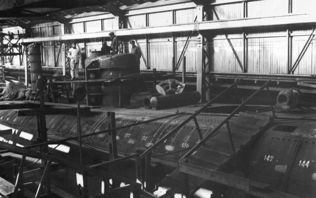
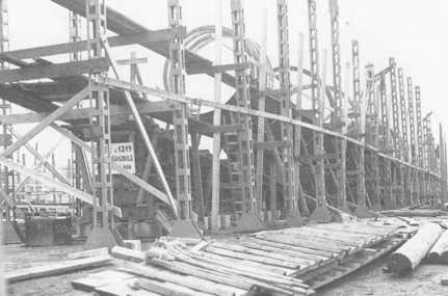
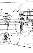
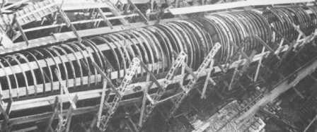
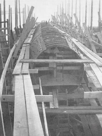
Construction of the resistant part of the hull

In 1934 the armament was modified, removing the 120/27 gun, and replacing it with a more modern (and long) 120/45 mm OTO Mod. 1931, installed in a more traditional “unprotected” arrangement on deck, forward of the conning tower. The two single 13.2 mm machine guns were also replaced with twin guns of the same caliber.

A special feature of the class was the periscope rangefinder, which could be raised or lowered by means of a rope lifting system, driven by an electric motor. Usable as an exploratory periscope (in addition to the two existing periscopes, attack and observation), it consisted of two distinct parts, a rangefinder and a periscope. The rangefinder was of the mono-static coincidence type. The periscope length was eight and a half meters, the base of the rangefinder was one and a half meters, and the apparatus was capable of 22 magnifications, could rise or depress by 15°, and had unlimited swing.

On the whole, the Balilla were judged to be successful submarines, robust, manoeuvrable and of good seaworthiness both on the surface and underwater (good seaworthiness, good manoeuvrability while diving), as also confirmed by the long and demanding test cruises that were made  in the Atlantic (by Balilla and Millelire during the “Decennial Air Cruise” of 1933) and in tropical seas (by Toti and Sciesa which, in 1933-1934, circumnavigated Africa). Their main flaws, according to some sources (e.g. “Submarines: An Illustrated History of Their Impact” by Paul E. Fontenoy), were a not exceptional stability and a certain slowness in dive times, the latter problem common to almost all Italian submarines. The auxiliary diesel engine also proved to be too unreliable for its original function – that of making long-range missions possible – so much so that it was decided not to install it on subsequent classes of submarines, in order to save precious space inside the hull (with the exception of the Admirals class, large long-range “cruiser submarines” built during World War II,  on which this concept was taken up).

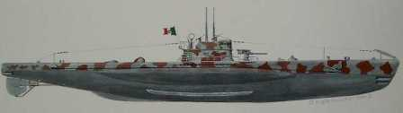
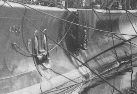
A fifth submarine of the Balilla class, the Humaitá, was built by the OTO for the Brazilian Navy (whose entire submarine, from its birth in 1914 to the fifties, was made up of Italian-built units: the first submarines in Brazil were three F-class boats, built by the FIAT-San Giorgio shipyard in La Spezia; after the Humaitá they were built for Brazil,  in 1937, three submarines of the Adua class, which together with the Humaitá represented the entire Brazilian submarine fleet during the World War II), which became interested in the new class while the project was still being studied.

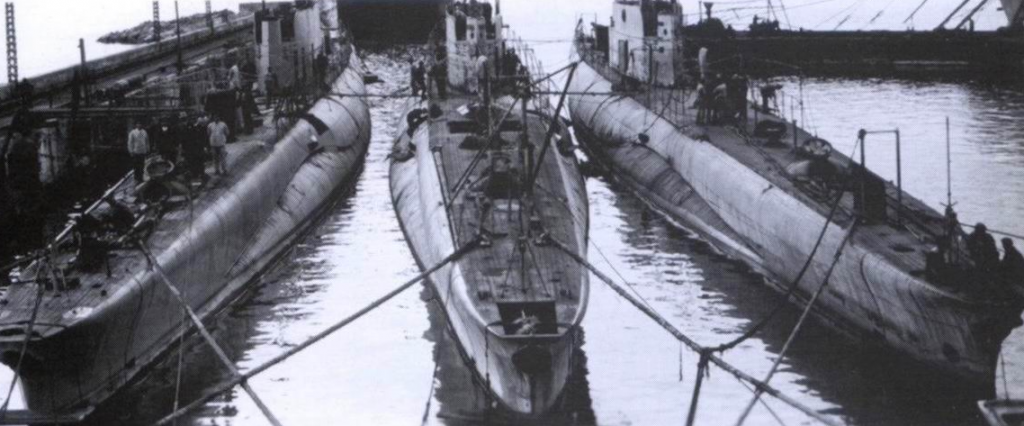
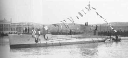
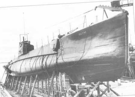
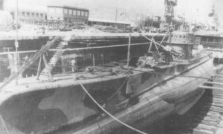
Balilla being fitted along Millelire and Humanità
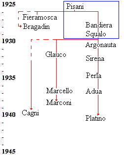
(From “Gli squali dell’Adriatico” by Alessandro Turrini)

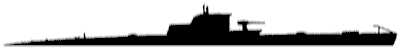
It was a modified version of the Balilla class, with a displacement of 1,390 or 1,450 tons on the surface and 1,884 submerged; the main differences compared to the Balilla were represented by the position of the diesel engines (produced by Ansaldo, instead of FIAT) and electric engines (placed further forward), in the absence of forward depth planes, in a different distribution of the ballast boxes, in the different caliber of the deck gun (102 mm, instead of the 120 of the Balilla), in the greater capacity for transporting and laying mines (16 weapons),  in the longer length of half a meter, in the slightly shallower draft (four meters, instead of 4.11) and in the slightly higher speed both on the surface (18.5 knots) and in submerged (9.5 knots). Ordered by Brazil in 1925, in addition to the four boats already laid down for the Italian Navy, it entered service in July 1929, the Humaitá would be decommissioned in the early fifties.

From the Balilla class was derived the design of the Calvi class of ocean-going submarines, built in three specimens in 1932-1935, which gave excellent results during the war. Elements of the Balilla design, starting with the total double hull structure, were also taken up in the design of the smaller medium-cruising submarines of the Argo class, which was also judged to be very successful and then reproduced and improved with the Flutto or Tritone class.

The Soviet Navy, which in 1925 obtained from Italy, through a naval mission, a copy of the Balilla class designs, incorporated various elements into the design of the (not very successful) Dekabrist class (six units built between 1927 and 1930), the first submarines built in the Soviet Union after the October Revolution.

In the course of their operational life, the submarine of the Balilla class received various improvements, on the basis of the experiences acquired.  After the first years of service, however, their efficiency declined due to the rapid deterioration of the material (especially of the engine systems, subject to frequent failures), and at the outbreak of World War II, with already twelve years of intense service (including ocean cruises and participation in the Spanish Civil War) on their shoulders, they were worn out boats of reduced efficiency,  which required long periods of work after each mission, even of short duration (their large size, moreover, made them unsuitable for use in the Mediterranean). After a few offensive missions, they were therefore assigned to training tasks or transport missions. Three of them were disarmed during the war and transformed into barges or pontoons (Balilla and Millelire already in 1941, Toti in 1943), the fourth (Sciesa) was lost at the end of 1942 during a transport mission. The historian Giorgio Giorgerini gives the following assessment: “… They were judged to be of excellent nautical qualities and excellent underwater maneuverability, qualities that were also demonstrated in the long cruises carried out by these submarines in distant warm and cold seas. A few deficiencies were recorded when they entered service, but this is quite normal when building units that in practice are still prototypes. They were a good testing ground for later boats, but by the time they entered the war in 1940 they were naturally outdated and old.”

Submarine Construction Types and Classes

There were four primary types of submarine and a very large number of classes. A fifth primary type, Balilla, should be considered unique.

Here is a list of the boats, construction types, and classes. This list only includes the main classes, thus one will not find foreign-built or midget submarines.

BoatConstruction TypeClassType
Adua600AduaSubmarine – Coastal
Alagi600AduaSubmarine – Coastal
Aradam600AduaSubmarine – Coastal
Ascianghi600AduaSubmarine – Coastal
Axum600AduaSubmarine – Coastal
Beilul600AduaSubmarine – Coastal
Dagabur600AduaSubmarine – Coastal
Dessiè600AduaSubmarine – Coastal
Durbo600AduaSubmarine – Coastal
Gondar600AduaSubmarine – Coastal
Lafolè600AduaSubmarine – Coastal
Macallè600AduaSubmarine – Coastal
Neghelli600AduaSubmarine – Coastal
Scirè600AduaSubmarine – Coastal
Tembien600AduaSubmarine – Coastal
Uarsciek600AduaSubmarine – Coastal
Uebi Scebeli600AduaSubmarine – Coastal
Ammiraglio CagniBernardisAmmiragliSubmarine – Oceanic
Ammiraglio CaraccioloBernardisAmmiragliSubmarine – Oceanic
Ammiraglio MilloBernardisAmmiragliSubmarine – Oceanic
Ammiraglio Saint BonBernardisAmmiragliSubmarine – Oceanic
ArchimedeCavalliniArchimedeSubmarine – Oceanic
Evangelista TorricelliCavalliniArchimedeSubmarine – Oceanic
Galileo FerrarisCavalliniArchimedeSubmarine – Medium Range
Galileo GalileiCavalliniArchimedeSubmarine – Medium Range
ArgoC.R.D.A.ArgoSubmarine – Coastal
VelellaC.R.D.A.ArgoSubmarine – Coastal
Argonauta600ArgonautaSubmarine – Coastal
Fisalia600ArgonautaSubmarine – Coastal
Jalea600ArgonautaSubmarine – Coastal
Jantina600ArgonautaSubmarine – Coastal
Medusa600ArgonautaSubmarine – Coastal
Salpa600ArgonautaSubmarine – Coastal
Serpente600ArgonautaSubmarine – Coastal
Antonio SciesaBalillaBalillaSubmarine – Oceanic
BalillaBalillaBalillaSubmarine – Oceanic
MillelireBalillaBalillaSubmarine – Oceanic
TotiBalillaBalillaSubmarine – Oceanic
Ciro MenottiBernardisBandieraSubmarine – Medium Range
Fratelli BandieraBernardisBandieraSubmarine – Medium Range
Luciano ManaraBernardisBandieraSubmarine – Medium Range
Santorre SantarosaBernardisBandieraSubmarine – Medium Range
CorridoniBernardisBragadinSubmarine – Minelaying
Marcantonio BragadinBernardisBragadinSubmarine – Minelaying
BrinCavalliniBrinSubmarine – Oceanic
GalvaniCavalliniBrinSubmarine – Oceanic
GuglielmottiCavalliniBrinSubmarine – Oceanic
Enrico TazzoliBernardisCalviSubmarine – Oceanic
Giuseppe FinziBernardisCalviSubmarine – Oceanic
Pietro CalviBernardisCalviSubmarine – Oceanic
Ettore FieramoscaBernardisFieramoscaSubmarine – Oceanic
AtropoCavalliniFocaSubmarine – Medium Range
FocaCavalliniFocaSubmarine – Medium Range
ZoeaCavalliniFocaSubmarine – Medium Range
GlaucoBernardisGlaucoSubmarine – Oceanic
OtariaBernardisGlaucoSubmarine – Oceanic
Alpino BagnoliniCavalliniLiuzziSubmarine – Oceanic
Capitano TarantiniCavalliniLiuzziSubmarine – Oceanic
Console Generale LiuzziCavalliniLiuzziSubmarine – Oceanic
Reginaldo GiulianiCavalliniLiuzziSubmarine – Oceanic
Da ProcidaCavalliniMameliSubmarine – Medium Range
MameliCavalliniMameliSubmarine – Medium Range
Pier CapponiCavalliniMameliSubmarine – Medium Range
SperiCavalliniMameliSubmarine – Medium Range
BarbarigoBernardisMarcelloSubmarine – Oceanic
Comandante CappelliniBernardisMarcelloSubmarine – Oceanic
Comandante Faa Di BrunoBernardisMarcelloSubmarine – Oceanic
DandoloBernardisMarcelloSubmarine – Oceanic
EmoBernardisMarcelloSubmarine – Oceanic
MarcelloBernardisMarcelloSubmarine – Oceanic
MocenigoBernardisMarcelloSubmarine – Oceanic
MorosiniBernardisMarcelloSubmarine – Oceanic
NaniBernardisMarcelloSubmarine – Oceanic
ProvanaBernardisMarcelloSubmarine – Oceanic
VenieroBernardisMarcelloSubmarine – Oceanic
Alessandro MalaspinaBernardisMarconiSubmarine – Oceanic
Guglielmo MarconiBernardisMarconiSubmarine – Oceanic
Leonardo Da VinciBernardisMarconiSubmarine – Oceanic
Luigi TorelliBernardisMarconiSubmarine – Oceanic
Maggiore BaraccaBernardisMarconiSubmarine – Oceanic
Michele BianchiBernardisMarconiSubmarine – Oceanic
MiccaCavalliniMiccaSubmarine – Minelaying
Ambra600PerlaSubmarine – Coastal
Berillo600PerlaSubmarine – Coastal
Corallo600PerlaSubmarine – Coastal
Diaspro600PerlaSubmarine – Coastal
Gemma600PerlaSubmarine – Coastal
Iride600PerlaSubmarine – Coastal
Malachite600PerlaSubmarine – Coastal
Onice600PerlaSubmarine – Coastal
Perla600PerlaSubmarine – Coastal
Turchese600PerlaSubmarine – Coastal
BausanBernardisPisaniSubmarine – Medium Range
Des GeneysBernardisPisaniSubmarine – Medium Range
Marcantonio ColonnaBernardisPisaniSubmarine – Medium Range
Vettor PisaniBernardisPisaniSubmarine – Medium Range
Acciaio600PlatinoSubmarine – Coastal
Alabastro600PlatinoSubmarine – Coastal
Argento600PlatinoSubmarine – Coastal
Asteria600PlatinoSubmarine – Coastal
Avorio600PlatinoSubmarine – Coastal
Bronzo600PlatinoSubmarine – Coastal
Cobalto600PlatinoSubmarine – Coastal
Giada600PlatinoSubmarine – Coastal
Granito600PlatinoSubmarine – Coastal
Nichelio600PlatinoSubmarine – Coastal
Platino600PlatinoSubmarine – Coastal
Porfido600PlatinoSubmarine – Coastal
Volframio600PlatinoSubmarine – Coastal
R10CavalliniRSubmarine – Transport
R11CavalliniRSubmarine – Transport
R12CavalliniRSubmarine – Transport
R3CavalliniRSubmarine – Transport
R4CavalliniRSubmarine – Transport
R5CavalliniRSubmarine – Transport
R6CavalliniRSubmarine – Transport
R7CavalliniRSubmarine – Transport
R8CavalliniRSubmarine – Transport
R9CavalliniRSubmarine – Transport
RemoCavalliniRSubmarine – Transport
RomoloCavalliniRSubmarine – Transport
Ruggiero SettimoCavalliniSettembriniSubmarine – Medium Range
SettembriniCavalliniSettembriniSubmarine – Medium Range
Ametista600SirenaSubmarine – Coastal
Anfitrite600SirenaSubmarine – Coastal
Diamante600SirenaSubmarine – Coastal
Galatea600SirenaSubmarine – Coastal
Naiade600SirenaSubmarine – Coastal
Nereide600SirenaSubmarine – Coastal
Ondina600SirenaSubmarine – Coastal
Rubino600SirenaSubmarine – Coastal
Sirena600SirenaSubmarine – Coastal
Smeraldo600SirenaSubmarine – Coastal
Topazio600SirenaSubmarine – Coastal
Zaffiro600SirenaSubmarine – Coastal
DelfinoBernardisSqualoSubmarine – Medium Range
NarvaloBernardisSqualoSubmarine – Medium Range
SqualoBernardisSqualoSubmarine – Medium Range
TrichecoBernardisSqualoSubmarine – Medium Range
CerniaC.R.D.A.TritoneSubmarine – Coastal
DenticeC.R.D.A.TritoneSubmarine – Coastal
FluttoC.R.D.A.TritoneSubmarine – Coastal
GorgoC.R.D.A.TritoneSubmarine – Coastal
GroncoC.R.D.A.TritoneSubmarine – Coastal
MareaC.R.D.A.TritoneSubmarine – Coastal
MurenaC.R.D.A.TritoneSubmarine – Coastal
NautiloC.R.D.A.TritoneSubmarine – Coastal
SparideC.R.D.A.TritoneSubmarine – Coastal
SpigolaC.R.D.A.TritoneSubmarine – Coastal
TritoneC.R.D.A.TritoneSubmarine – Coastal
VorticeC.R.D.A.TritoneSubmarine – Coastal

Submarines Class Type Cavallini

Introduction

Two officers of the Regia Marina’s “Genio Navale” (engineering) generated the most popular submarine designs in use by the Italian Navy’s submarine fleet: Cavallini and Bernardis. The “Cavallini” were produced in seven distinct classes and they all evolved from the “Mameli Class”, built starting in 1925. Two years later came the “Settembrini Class” from which, in 1931, evolved the “Archimede Class”.

Archimede

Brin

Foca

Liuzzi

Micca

The subsequent classes, “Brin” in 1936, and “Liuzzi” in 1937, were further evolutions, while the minelayers “Micca” (1931) and “Foca” (1936), and eventually the transport class “R” (1941) were partial evolutions, or adaptations of the original design. Technical differences between the various classes were in some areas modest, while in other areas far greater.

The evolution of the submarine type Cavallini

Ultimately, they could all be classified as an evolution of the original “Mameli” class due to the adoption of the partial double hull, better known as the “Sattletank” (saddle tank) design, typical of the German U-Boats. The partial external hull extended for about 70% of the total length of resistant hull. All the “Cavallini” were built by the shipyard Tosi of Taranto, and the various boats of the class “R” assigned to other shipyards in the North were never completed. The first class designed by Cavallini in collaboration with the Tosi of Taranto was, as already mentioned, the “Mameli“ class. These boats were known for their strong design, good speed and maneuverability, and especially excellent habitability. These characteristics were maintained throughout the evolution of the d

Design and Construction

Since the creation of the first submarines, and not until the introduction of more revolutionary designs later in WW II and in the post-war period, submarines were made up of three distinct components: inner hull, outer hull, and superstructure.

The Saint Bon under early construction. The circular beams are clearly visible
(Photo Turrini)

The inner hull, also known as the pressure hull, was usually built of various cylindrical sections sealed at both ends by semispherical cups from which protruded the torpedo tubes. A second cylindrical area was positioned amidships and was enclosed in the conning tower. The outer hull was the seaworthy external shape of the submarine designed for navigational qualities. Within this outer shell there were compartments utilized for the storage of fluids (ballast or oil), external ballast or compensation tanks, and very little unutilized space.

The two half spherical extremities of the Ammiraglio Caracciolo where are clearly visible the opening for the torpedo tubes
(Photo Turrini)

The superstructure was constructed on top, aft and forward of the hulls and giving the submarine a flat deck, a cruiser-like bow and a round stern. This part was usually completely open to the ocean and seawater drained through wide openings above the outer hull, or smaller cutouts placed along the whole profile. The “Settembrini” class, which followed the “Mameli” had the shape of the hull improved, thus improving the navigational qualities of the vessel. Although larger (more displacement, longer and wider hull), the “Settembrini” class was capable of reaching 18 knots versus the 17.2 of the “Mameli”, even though they were sharing the identical power plant.

All the “Cavallini” class submarines were of the saddle tank, or partial double hull design. The “Mameli” class had a perfectly cylindrical pressure hull made of cylindrical beams (reinforcement rings) positioned 500 mm (19.69 in) apart and to which were riveted multiple steel plates positioned in a brick layer fashion (each plate tended to overlap the other half of the adjacent plates). Plates were made of nickel steel with a breaking point of 60 kg/mm2 (853.4 psi), and an enervating point of 42 kg/mm2 (597.4 psi). Plates were 18 mm (0.7087 in) thick around midship and 16 mm (0.6299 in) thick toward the extremity. The forward and aft sections were tapered so that the internal circumference of the supporting beams was larger in the central compartments than the extreme ones. Each plate was secured by a double row of rivets, and an extra plate was installed inside and outside of the riveted area.

R.Smg. Romolo

The entire pressure hull was divided into five primary compartments plus the control room. Starting aft, the first compartment was the aft torpedo room which also included the electric motors, followed by the diesel engine rooms, the control room, the officer and petty officer quarters and first battery holds, and finally the forward torpedo room and the second battery hold. Above the control room there was a smaller chamber (conning tower). The two periscope sleeves were also considered parts of the pressure hull.

A watertight bulkhead capable of withstanding water pressures up to 40 atmospheres (853.4 psi) separated each compartment. Later evolutions of the “Cavallini” had this bulkhead reinforced. The outer hull was made of 7 mm (0.2756 in) steel, and as already mentioned, the space in between the two hulls was used to stow diesel fuel and ballast water. On each side (in each saddle) there were two water tanks and a diesel fuel tank. The upper deck was surfaced with teak wood slats bolted to the metal frame. The shape of the bow varied from class to class. The “Mameli” had a round bow and a sloped stern. The “Settembrini” had the bow redesigned in more geometrical lines. The same designed was kept on the “Archimede”, but the later classes returned to a round bow, while the “Liuzzi” also had an elongated stern.

Propulsion

Diesel Engines

The “Mameli” class was powered by two Franco Tosi “S8” eight cylinder diesel engines capable of producing 1,500 HP (1119 Kw). These were four-stroke motors with a primary crankshaft to which were connected the pistons; they could not be reversed (they only rotated one way). The engines were directly connected to a four-stage air compressor which produced air at a pressure of 70 Kg/cm2 m (995.6 psi) and which was also used (in reverse) to start the engines. The “Settembrini” kept the same engine configuration, but the “Archimede and “Brin” were equipped with the new Tosi E6, a six-cylinder, two-stroke reversible 1,700 HP (1268 Kw) diesel engine which, on the “Liuzzi” were replaced by the EG, a similar model with about 10 extra horsepower. The various power plants did not directly effect the surface speed of the boats, but rather their endurance.

The 8-cylinder diesel engine Tosi S8 capable of generating 1,500 HP
(Photo Turrini)

The “Settembrini” were faster than the Mameli (18 v. 17.2 knots ) and the “Brin” were faster than the poorly conceived “Archimede” (17.47 v. 17 knots), and finally the “Liuzzi” were technically capable of 17.8 knots. With continuous use and the general aging of the boats, these values became hardly achievable, especially toward the end of their operational livesMine

. On surface navigation, the engines were connected to the primary axels via a clutch joint, while the axels were connected to the propeller shafts by a geared joint. The geared joints could be disconnected from the propeller shaft and connected to the electric motors, thus turning them into dynamos for the production of direct current. While submerged, the clutch joints were fully disengaged. The two diesel engines received their supply of fresh air from an intake place above deck within the conning tower. The intake was protected by a large valve, which, while the boat was submerged, was sealed.

Electric Motors

On the “Mameli” the two electric motors (double coaxial armature winding) were produced by C.G.E. and capable of producing up to 550 HP (410.1 Kw) each. All subsequent models were fitted with motors produced by Ansaldo. The motors on the “Mameli” were powered by direct current and could be supplied with 55, 110 or 220 volts. Each motor could be run at full speed (550 HP) for one hour, at 416 HP for three hours and at 66 HP in continuous motion. The Ansaldo installed on the “Settembrini” could also produce 550 HP, but those on the “Archimede” were capable of 700 HP (522 Kw), while the “Brin” were reduced to 650 HP and the Liuzzi to 625 HP. The difference between the various power plant solutions allowed for various endurance at maximum speed; the “Settembrini” performed worst (7 miles at 8 knots), while the “Brin” second series performed best (10 miles at 8.6 knots).

Batteries

On the “Mameli” and the “Settembrini” there were two 56 cell storage batteries. Each cell was of the type 30 M.A.S. 870-5 produced by the SGIAE of Melzo (near Milan) and weighed 750 kg (1653 lb) The total weight of all cells was 84 tons (92.59 short tons). The batteries could deliver 5,150 amps in one hour, 7,500 amps in three (2,500 amps/hour), and 11,500 amps in twenty hours (575 amps/hour). This configuration was altered on the “Archimede” and these boats were fitted with a total of 128 cells divided into two compartments. The cells were of the type “Tudor Ironclad” and could deliver 4,270 amps in one hour, and 9,350 amps in twenty hours (565.5 amps/hour). The “Brin” were fitted with 132 cells also divided into two compartments. These cells were made by Scaini and could deliver 4,650 amps in one hour, 7,950 amps in five (1,590 amps/hour), 9,050 amps in ten (905 amps/hour), and 9,700 amps in twenty hours (485 amps/hour). The “Liuzzi” received smaller cells weighing 508 Kg (1120 lb) and produced by S.G.I.A.E. Each. There were a total of 232 cells, also divided into two compartments of 116 each, and could deliver 3,200 amps in one hour, 4,750 amps in three (1,583 amps/hour), and 7,300 amps in twenty-five hours (792 amps/hour). This configuration made the “Liuzzi” improve the original underwater range of the “Mameli”, 80 miles at 4 knots, to a respectable 110 miles at the same speed. Each cell was made of multiple positive and negative plates made of lead, each with common terminals, separated by insulators. The plates were immersed in an electrolyte solution made of pure water and pure sulfuric acid with a specific gravity of 1.250 when fully charged. Each cell produced approximately two volts and was permanently wired in series. Each of the two battery groups could be operated independently or in parallel. On the “Mameli” each battery group was divided into two busses, each composed of 28 cells (28 x 2 volts = 56 volts).

Air Systems

The compressed air system was one of the most important systems on the submarine. It was used to blow the ballast tanks, fire torpedoes, and to start the main engines. Without a functional air system the submarine became inoperable. Docking facilities were usually provided with the necessary high-pressure air supply so that the submarine would not have to produce its own. Air tanks dented to accumulate condensed moisture (water), thus they were regularly drained for maintenance. On the “Mameli” and “Settembrini” the primary air compressor was installed in the control room. It was build by San Giorgio and capable of pressurizing air up to 210 kg.cm2 (2987 psi) and producing 9 liters per minute (0.31 ft3 per minute). The compressor was powered by a 50 HP electric motor. There were also two super compressors, also built by San Giorgio, capable of boosting air pressure from 70 to 225 kg.cm2 (995 to 3200 psi), and producing 9 liters per minute. They were driven by a 10 HP electric motor rotating at 670 r.p.m. This system received air from the two compressors built into the diesel engines and air was stored into three tanks with a total capacity of 4,580 liters (162 ft3).

The “Archimede” had the air supply increased to 8,000 liters (282 ft3) and pressure reduced to 200 kg.cm2. The “Brin” probably maintained the same configuration, while the “Liuzzi” were equipped with a total of 5 tanks for a total capacity of 10,000 liters (353 ft3). Air was used to exhaust the ballast tanks only under emergency conditions; usually these tanks were exhausted utilizing two rotor-compressors of the type Reavel-Cerpelli, capable of producing 30 m3 (1059 ft3) of air per minute at a pressure of about 1.6 to 1.8 atmospheres. Each compressor absorbed 60 HP and rotated at about 1,600 RPM. These compressors could only be used when the submarine had at least the conning tower out of the water so that the hatch could be open to supply external air. The “Archimede” were fitted with four pumps, two capable of 50 t at 150 meters, and two of 30 t also at 150 meters. There were also two low-pressure blowers (less than 2 atmospheres) capable of 30 m3. The blowers shared the same electric motors as the pumps. The boats were also equipped with emergency pumps driven by low-pressure air or manpower.

Air Filtering System

The “Archimede”, and probably the previous classes, were equipped with an air regeneration system for the removal of CO2 (Carbon Monoxide). There were also a dozen 48-liter oxygen tanks loaded up to 150 Kg/cm2, and which were used to oxygenate the depleted air while submerged. The submarine was equipped with external hookups so that, in case of malfunction, a support ship could blow the ballast tank and also provide breathable air.

Crew Quarters

On the “Mameli” the officer’s area was arranged with four foldable bunks, which would turn into two sofas, much like on Italian train cars. The petty officers’ quarters had a similar arrangement, while the crew was divided between the two torpedo rooms. On the “Liuzzi” there were 18 foldable bunks in each torpedo room.

Galley

There were two galleys, one powered by electricity and located in the forward torpedo room, and one burning diesel oil and located within the conning tower. On the “Liuzzi” the internal galley was relocated starboard in the electric motors room.

Heads

There were three heads inside the submarine, and two inside the conning tower. Naturally, the galley and latrines inside the conning tower could only be used while on the surface.

Fresh Water

The submarine had a total reserve of about 13.2 t of fresh water. On the “Brin” the water supply was increased to 14.86 t divided over 4 tanks. In the Liuzzi the water supply was increased to 15 t and an electric water purification system was also installed.

Refrigeration

Oddly enough, on the “Archimede” the refrigerator for the production of ice and the preservation of fresh foodstuff was located in the aft torpedo room, and was made by Frigidaire. On the “Brin” the refrigerator was of domestic manufacturing, of the type Bazzi utilizing methylchlorid (CH3Cl). The “Liuzzi” utilized a system produced by the firm Canepa, and also utilizing methylchlorid.

Crew

The “Mameli” had a crew of 5 officers and 44 enlisted. The “Settembrini” had 6 officers and 50 enlisted, later reduced to 49 on the “Archimede”. The “Brin” had 7 officers and 47 enlisted, later increased to 50 on the “Liuzzi”.

Safety Systems

Between the torpedo rooms and the internal compartments, the engineers had placed two Gerolami-Arata lifts. These devices consisted of a sealed chamber which would float to the surface by buoyancy and could then be retrieved by a tether connected to the bottom of it and secured to a winch. Each time the chamber was released it could take one crew member to the surface without incurring any of the dangers caused by exposing the human body to the high water pressure of the depths. Due to the presence of this device, the bulkhead between the torpedo rooms and the inner compartments was equipped with two hatches.

Communication, Radio, and Navigational Systems

Navigation

The “Archimede” was equipped with a gyrocompass of the type Sperry installed in the forward torpedo room which had three repeaters installed in various compartments (and also in the wheelhouse). There was also a magnetic compass installed in a water-proof casing on deck with a repeating station in the control room.

The gyrocompass received its directive from a high speed spinning gyroscope driven by electric motors. Its directive action is based on the mechanical laws governing the dynamics of rotating bodies. When any object is spinning rapidly it tends to keep its axis pointed in the same direction. The gyrocompass consists of a spinning gyroscope, made north-seeking by placing a weight below the axis, which is mounted in gimbals so that the movements of the submarine do not effect its position. A dial mechanically connected to the gyrocompass has the points of the mariner’s compass marked on it and indicates the submarine’s true course.

Radio

On the “Mameli” the radio equipment consisted of a 3 kW short-wave radio set (utilizing tubes), a 3 kW converter made by Marelli, a received model R.M. 1926 for short waves (300 and 1,200 meters), and second short-waves received (30 and 90 meters). On the “Archimede” the radio had only 1.5 kW. The antenna consisted of a stay and cables running forward and , aft almost the full length of the boat. The radio room was installed in the officer quarters, near the hatch leading to the control room. The “Archimede” were equipped with a radio localizer apparatus mounted on the conning tower and controlled from the radio room.

There was a hydrophone system connected to two transmitters mounted on the saddles and capable of emitting 150 watts. There were four receivers, mostly placed aft. On later classes (Brin), the number of receivers was substantially increased (16). On the “Mameli” the hydrophone station was placed in the aft torpedo room. On the “Archimede” Tosi installed a “Langevin-Florrison” echo sounder.

General announcing system

All “Cavallini” were equipped with an announcing system. Each compartment could communicate with a central station located in the control room via a speaker microphone system.

Alarm system

The “Cavallini” were equipped with a klaxon operated from the control room. Upon sounding the alarm, all hatches would be secured and the engineers would commence the diving procedures securing the diesel engines’ intake and exhaust valves.

Telephone call system

The “Cavallini” were equipped with two buoys situated on deck and attached to a retrieval system. If necessary, the buoys could be released and floated to the surface, giving surface units a telephone connection to the submarine.

Periscope

There were two periscopes produced by the firm San Giorgio. The forward one, used to attack, was 8.5 meters long, while the aft one, used for exploration, was 11.5 meters long. The attack periscope was used in the small chambers placed above the control room, while the exploration one was used below, in the control room. Typical of Italian submarines, the periscope sleeves extended considerably from the conning tower and were enclosed in a light metal structure quite visible from a distance. In 1941, the remaining “Liuzzi” had the light structure removed and the sleeves reduced in size. Similar changes were made to the “Brin”, the remaining “Settembrini”, and the “Mameli”

Controls

When the “Cavallini” were on the surface, they operated like any other boat demonstrating good seaworthiness. Maintaining the various ballast tanks full of air provided buoyancy.

Rudder

The rudder (semi-compensated) was controlled electrically from the control room, or manually for the aft torpedo room. Also, there was a wheel in the conning tower in an enclosed wheelhouse. On the “Mameli” the rudder had a total surface of 4.85 m2.

Diving Planes

As standard on most submarines, the “Cappellini” were equipped with two sets of diving planes. The forward planes were collapsible (folded upward) for surface navigation and were placed above the waterline; their total surface was 4.96 m2 (on the “Mameli”). The aft planes were fixed and placed below the waterline in line with the two propellers and their surface was 5.14 m2 (on the “Mameli”). The forward planes were used to control depth, while the aft ones were used to control the angle of the boat. The planes were controlled electrically from the control room, but could also be manually operated from the torpedo rooms.

Anchors

The “Archimede” were equipped with a primary anchor of the type Hall of 650 Kg and a smaller anchor type Admiralty of about 150 kg. There were two winches, one forward and one aft.

Weapons

Torpedoes

All “Cavallini” excluding the “Mameli” were fitted with four torpedo tubes aft and four forward. The “Mameli” had only two tubes aft. All tubes were loaded before leaving port and two extra torpedoes were stowed in each compartment giving the “Mameli” a total of 10 torpedoes, while all other boats had 12. Torpedoes were loaded through a special hatch and the operation was very laborious. Once at sea, torpedoes could be removed from the tubes for limited maintenance (fuel topping).

Range, speed and direction of the weapons could be configured while they were inserted in the tubes. The tubes, produced by Tosi, could take a variety of 21’ (533 mm) torpedoes produced both by Whitehead and “Silurificio Italiano”. Similar to the Royal navy, the Regia Marina did not experience the kind of massive torpedo failure which plagued the U.S. Navy and the Kriegsmarine. Italian weapons were reliable, but left a visible trail thus making them easy to spot.

Smaller weapons

Each boat was equipped with a small armory containing rifles and side arms.

Deck Guns

The first two “Cavallini” classes were fitted with a 4” (102) mm deck gun caliber 35 produced by O.T.O. (Model 1931, 35 and 38). These guns had a maximum range of 14,500 meters, but the practical range, due to the simplicity of the optical range-finder, was much lower. Later classes were fitted with the newer 100 mm caliber 43, while the “Liuzzi” received a caliber 47. The “Cavallini” carried 22 kg Ap shells or smaller 13.8 kg. conventional shells. The “Mameli” had a reserve of 150 shells, increased to 200 on the “Settembrini”, 230 on the newer classes and further increased to 290 on the “Liuzzi”. The muzzle velocity, originally at around 730 m/s, was later increased to 840 m/s. A well-trained gunnery team could fire eight shells per minute. Shells were loaded from the stowage area below onto the main compartment and from there pushed up to the deck through a tube. Since there are no specifications for a mechanical or hydraulic hoisting system, it is assumed that the shells were pushed by hand. The gunners also had access to a ready storage area built into the conning tower and secured by a watertight hatch.

The Brin’s deck gun in is awkward position on top of the conning tower.
(Photo courtesy Erminio Bagnasco and Achille Rastelli)

The “Mameli” and the “Settembrini” had a single gun mounted forward of the conning tower. The “Archimede” had a second gun installed aft of the conning tower. The “Brin” were the most unusual; seeking to provide the gunners with a better platform protected from the elements and with a greater range of excursion, the designers fitted the gun on top of the conning tower. This very unusual installation, resembling some British classes, gave the “Brin” their unusual silhouette. Eventually, it was soon discovered that the arrangement was not satisfactory and never repeated. The “Liuzzi” returned to the field-tested single gun mounted aft.

Machine Guns

All “Cavallini” were equipped with the famous Breda Model 1931 13.2 mm anti-aircraft machine gun. These guns were mounted on a single support on the “Mameli” and “Archimede” and on double mounts on all other classes. The guns were installed on a retractable mount which would recede into a water-tight tube protected by a small hatch. Upon emerging, the gunners had to simply release the hatch, lift the guns out of the enclosure, install clip and fire. Each clip contained 30 rounds and the gun could fire up to 400 rounds per minute at a range of 2,000 meters. The “Mameli” and “Settembrini” had a reserve of 6,000 rounds, reduced on the “Archimede” to 3,000 but later restored on the later classes, with the exception of the “Liuzzi” which had a reserve of 12,000 rounds. As with all Italian submarines, toward the end of the conflict it was discovered that the 13.2 mm guns were insufficient in downing large American bombers protected by a thick armor.

Mines

On the MICCA, the total capacity of the mine holds was 40 weapons. The mines, 20 aft and 20 forward, were lodge in pairs of two on rails. The mines were loaded from hatches located forward and aft of the deck guns. Each hutch would open on the deck below from which another hatch led to the holds.

The mine holds of the Foca

Each hold had its own separate ejection mechanism, basically a simple hatch opening downward and allowing the mines to exit the hull by gravity. The low speed of a submerged submarine and the ability of the crew to accurately measure bearing and speed would allow for the precise delivery of the weapons in the form of mine fields.

Submarines Class Type Bernardis

Introduction

Two officers of the Regia Marina’s “Genio Navale” (engineering) generated the most popular submarine designs in use by the Italian Navy’s submarine fleet: Cavallini and Bernardis. The “Bernardis” were produced in several classes and they all evolved from the “Vector Pisani Class”, built starting in 1925. Three years later came the “Bandiera Class” and two years later, in 1930, the almost identical “Squalo Class”. Later evolutions, namely the “Glauco Class” in 1932, the “Marcello Class” in 1937”, and the “Marconi Class” in 1939, made the Bernardis true oceanic submarines and they are covered in a different section of this site.

The evolution of the early Bernardis

Colonel Curio Bernardis, later General, began the design of a new class of submarines merging the previous design by Laurenti with new, and quite innovative ideas. The goal was to create boats capable of reaching greater depths relying more on the structural integrity of the external part of the resistant hull, rather than the thickness of the internal beans. Bernardis’ design called for a traditional circular hull enclosed at both ends by a semispherical cup. Whiel the ballast tanks were positioned at the end of the resistant hull, inside this there was an additional tank which allowed for high dept operations since it could be emptied both utilizing compressed air and pumps.

The Vector Pisani
(Photo Turrini)

The original Bernardis were not very successful, but their evolution gave birth to the Marcello and Marconi classes, some of the most successful products of the Italian submarine shipbuilding effort. The Vector Pisani Class included four boats built between 1925 and 1929, and as soon as they underwent testing at sea a serious flaw was immediately discovered: the boat tended to roll quite heavily. To overcome this serious deficiency, the shipyard added some small saddle tanks which, while partially solving the problem, caused the surface speed to drop from 17 to 15 knots, and the submerged one from 10 to 8. To improve stability, some of the equipment was rearranged within the delicate balance allowed by submarine construction.

Mameli

Pisani

Squalo

Eventually, these saddle tanks were integrated in the project and become part of the Bernardis design. Unfortunately, while the problem was still undergoing studying on the Pisani, the Bandiera were already in advanced state of completion, thus they also had to be retrofitted. Furthermore, on the Bandiera another problem had to be corrected, the boat tendency to dip down by the bow. This problem was resolved by installing a special auto-filling tank which, while the unit was on the surface, would stay empty and give extra buoyancy, while in immersion would fill itself up. Further modifications to the Bardiera gave this class the unique bow which earned the four boats the nickname of “big nose”, or “nasone”. Unfortunately, even the third evolution of this series of submarines, the “Squalo Class”, was laid down too soon and they had to be heavily modified. Eventually, the first 12 boat of the Bernardis type laid the foundations for future design, first the 2 “Glauco” and then the 11 Marcello and 6 Marconi.

Design and Construction

Since the creation of the first submarines, and not until the introduction of more revolutionary designs later in WW II and in the post-war period, submarines were made up of three distinct components: inner hull, outer hull, and superstructure. The inner hull, also known as the pressure hull, was usually built of various cylindrical sections sealed at both ends by semispherical cups from which protruded the torpedo tubes. A second cylindrical area was positioned amidships and was enclosed in the conning tower. The outer hull was the seaworthy external shape of the submarine designed for navigational qualities. Within this outer shell there were compartments utilized for the storage of fluids (ballast or oil), external ballast or compensation tanks, and very little unutilized space.

The DELFINO still on the slip and without the saddle tanks.
(Photo Turrini)

The superstructure was constructed on top, aft and forward of the hulls and giving the submarine a flat deck, a cruiser-like bow and a round stern. This part was usually completely open to the ocean and seawater drained through wide openings above the outer hull, or smaller cutouts placed along the whole profile. The “Pisani” class, as already mentioned, had the shape of the hull modified with the additional of small saddle tanks, thus improving the navigational qualities of the vessel. Due to these alterations, the speed of the first three classes (Pisani, Bandiera and Squalo) would be limited to only 15 knots, while later classes would reach 17 and 18 knots.

All the “Bernardis” class submarines were of the simple hull design with double internal ballast tank. The Pisani Class had a perfectly cylindrical pressure hull made of cylindrical beams (reinforcement rings) positioned 500 mm (19.69 in) apart and to which were riveted multiple steel plates positioned in a brick layer fashion (each plate tended to overlap the other half of the adjacent plates). Plates were made of nickel steel (3% nickel) with a breaking point of 60 kg/mm2 (853.4 psi), and an enervating point of 42 kg/mm2 (597.4 psi). Plates were 20 mm (0.7874 in) thick around midship and 13 mm (0.5118in) thick toward the extremity. The following class, the Pisani, had the rings positioned 600 mm (23.62 in) apart and the steel plates were reduced to 18.5 mm (0.7283 in) and 15.5 mm (0.6102 in)

The forward and aft sections were tapered so that the internal circumference of the supporting beams was larger in the central compartments than the extreme ones. Each plate was secured by a double row of rivets, and an extra plate was installed inside and outside of the riveted area.

The entire pressure hull was divided into six primary compartments. Starting aft, the first compartment was the aft torpedo room which also included the electric motors, followed by the diesel engine rooms, the control room, the officer and first battery holds, the N.C.O.s quarters and second battery hold, and finally the forward torpedo room. Above the control room there was a smaller chamber (conning tower) made of diamagnetic steel. The two periscope sleeves were also considered parts of the pressure hull and the periscope wells protruded into the resistant ballast tank.

A watertight bulkhead capable of withstanding water pressures up to 40 atmospheres (853.4 psi) separated each compartment, excluding the two battery holds which were divided by a bulkhead resisting only 10 atmospheres (213.3 psi). The small water resistant chamber in the conning tower, as already mentioned, was made of diamagnetic steel, 25% nickel-based steel, thus allowing for operation of a magnetic compass and or radio equipment.

Drawings

Aft Planes

Battery hold

Diesel Engine

Electric motors

Deck gun

Crew quarters

Rudder

Aft tanks

Forward tanks

The main and crash tanks

Torpedo tubes

Propulsion

Diesel Engines

The “Pisani” class was powered by two Franco Tosi “K 6” six cylinder diesel engines capable of producing 1,350 HP. These were four-stroke motors with a primary crankshaft to which were connected the pistons; they could not be reversed (they only rotated one way). The engines were directly connected to a four-stage air compressor which produced air at a pressure of 70 Kg/cm2 m (995.6 psi) and which was also used (in reverse) to start the engines. The “Bandiera” and the “Squalo”were equipped with the new FIAT Q 426, a six-cylinder, two-stroke reversible 1,500 HP diesel engine. The two power plants did not directly effect the surface speed of the boats, but rather their endurance.

The three classes had almost similar performances with the “Pisani” rated at 15 knots, and the “Bandiera” and “Squalo” at 15.1 knots. With continuous use and the general aging of the boats, these values became hardly achievable, especially toward the end of their operational lives. On surface navigation, the engines were connected to the primary axels via a clutch joint, while the axels were connected to the propeller shafts by a geared joint. The geared joints could be disconnected from the propeller shaft and connected to the electric motors, thus turning them into dynamos for the production of direct current. While submerged, the clutch joints were fully disengaged. The two diesel engines received their supply of fresh air from an intake place above deck within the conning tower. The intake was protected by a large valve, which, while the boat was submerged, was sealed.

Electric Motors

On the “Pisani” the two electric motors (double coaxial armature winding) were produced by C.G.E. (Compagnia General Elettricità, Milan) and capable of producing up to 550 HP (410.1 Kw) each. The “Bandiera” were fitted with motors produced by Savigliano, while the “Squalo” received motors produced by C.R.D.A.

The motors on the “Pisani” were powered by direct current and could be supplied with 55, 110 or 220 volts. Each motor could be run at full speed (550 HP) for one hour, at 416 HP for three hours and at 66 HP in continuous motion. The Savigliano installed on the “Bandiera” could produce 650 HP each; those on the “Squalo” were also capable of 650 HP (522 Kw). The difference between the various power plant solutions allowed for various endurance at maximum speed; the “Pisani” and the “Bandiera” were capable of 8.8 miles at 8.2 knots, while the “Squalo” was only capable of navigating 7 miles at 8 knots.

Batteries

On the “Pisani”, “Bandiera” and :Squalo” there were two 56 cell storage batteries; later Bernardis had them increased to 132. On the “Pisani”, each cell was of the type 30 M.A.S. 870-5 produced by the SGIAE of Melzo (near Milan) and weighed 750 kg (1653 lb) The total weight of all cells was 84 tons (92.59 short tons). The batteries could deliver 5,150 amps in one hour, 7,500 amps in three (2,500 amps/hour), and 11,500 amps in twenty hours (575 amps/hour).

This configuration was identical to the “Mameli”, a class designed by Cavallini. This configuration was altered on the “Bandiera” and these boats were fitted with 112 Hensemberger R.M 865/28, batteries these with slightly different performaces (5,200 amps for one, 7,680 for 3 hours, 10,000 for10 hours and 11,000 for 20 hours). The “squalo” received batteries with far less performance; 4,270 amps for one, 6,380 for 3 hours, 8,400 for10 hours and 9,350 for 20 hours

Air Systems

The compressed air system was one of the most important systems on the submarine. It was used to blow the ballast tanks, fire torpedoes, and to start the main engines. Without a functional air system the submarine became inoperable. Docking facilities were usually provided with the necessary high-pressure air supply so that the submarine would not have to produce its own. Air tanks tended to accumulate condensed moisture (water), thus they were regularly drained for maintenance.

On the Bernardis the primary air compressor was installed in the compartment forward of the control room. It was build by San Giorgio and capable of pressurizing air up to 200 kg.cm2 (2845 psi). The compressors were powered by electric motor. There were also two super compressors, also built by San Giorgio, capable of boosting air pressure from about 70 to 200 kg.cm2 (995 to 2845 psi). This system received air from the two compressors built into the diesel engines and air was stored into tanks with a total capacity of 6,202 liters (219 ft3).

These compressors could only be used when the submarine had at least the conning tower out of the water so that the hatch could be open to supply external air. There were also two low-pressure blowers type Reavel-Cerpelli (less than 1.7 atmospheres) capable of 30 m3. The blowers shared the same electric motors as the asset pumps, each capable of moving about 60 tons of water per hour. In case of emergency, the pumps used to launch torpedoes, each capable of about 30 tons per hours, could also be used to move ballast water. The boats were also equipped with emergency pumps driven by low-pressure air or manpower. These hand-operated pumps were capable of about 120 liters per hour (4.238 ft3/h)

Air Filtering System

The Bernardis were equipped with an air regeneration system for the removal of CO2 (Carbon Monoxide). There were also oxygen tanks loaded which were used to oxygenate the depleted air while submerged. The submarine was equipped with external hookups so that, in case of malfunction, a support ship could blow the ballast tank and also provide breathable air.

Crew Quarters

On the early Bernardis the officer’s area was arranged with four bunks, which would turn into two sofas, much like on Italian train cars, and a private cabin for the captain. The crew was divided between the two torpedo rooms, N.O.C. aft and sailors forward.

Galley

There were two galleys, one powered by electricity and located in the forward torpedo room, and one burning diesel oil and located within the conning tower.

Heads

There were three heads inside the submarine, and two inside the conning tower. Naturally, the galley and latrines inside the conning tower could only be used while on the surface.

Fresh Water

The “Pisani” had a total reserve of about 15 m3 (529.7 ft3) of fresh water, later reduced to 11.246 m3 (397.1 ft3) on the “Bandiera”. From the “Bandiera” on, these boat received an electric distillatory device type Kirkaldy capable of producing about 600 liters (21.19 ft3) of distilled water every 24 hours.

Refrigeration

Oddly enough, on the “Pisani” the refrigerator for the production of ice and the preservation of fresh foodstuff was located in the aft torpedo room, and was made by Frigidaire. On the “Bandiera” it was replaced by a new machine produced by Glacia.

Crew

The “Pisani” had a crew of 5 officers and 44 enlisted. The “Bandiera” and the “Squalo” had 5 officers and 47 enlisted. On later Bernardis, the crew was increased to 57.
Safety Systems

Between the torpedo rooms and the internal compartments, the engineers had placed two Gerolami-Arata lifts. These devices consisted of a sealed chamber, which would float to the surface by buoyancy and could then be retrieved by a tether connected to the bottom of it and secured to a winch. Each time the chamber was released it could take one crewmember to the surface without incurring any of the dangers caused by exposing the human body to the high water pressure of the depths. Due to the presence of this device, the bulkhead between the torpedo rooms and the inner compartments was equipped with two hatches.

Communication, Radio, and Navigational Systems

Navigation

The Bernardis were equipped with a gyrocompass with repeaters installed in various compartments. There was also a magnetic compass. The gyrocompass received its directive from a high speed spinning gyroscope driven by electric motors. Its directive action is based on the mechanical laws governing the dynamics of rotating bodies. When any object is spinning rapidly it tends to keep its axis pointed in the same direction. The gyrocompass consists of a spinning gyroscope, made north-seeking by placing a weight below the axis, which is mounted in gimbals so that the movements of the submarine do not effect its position. A dial mechanically connected to the gyrocompass has the points of the mariner’s compass marked on it and indicates the submarine’s true course.

Radio

On the “Pisani” the radio equipment consisted of a 3 kW short-wave radio set (utilizing tubes). The antenna consisted of a stay and cables running forward and aft almost the full length of the boat. The radio room was installed in the control room.

Hydrophones

There was a hydrophone system connected to transmitters mounted on the hull.

General announcing system

All “Bernardis” were equipped with an announcing system. Each compartment could communicate with a central station located in the control room via a speaker microphone system.

Alarm system

The “Bernardis” were equipped with a klaxon operated from the control room. Upon sounding the alarm, all hatches would be secured and the engineers would commence the diving procedures securing the diesel engines’ intake and exhaust valves.

Telephone call system

The “Bernardis” were equipped with two buoys situated on deck and attached to a retrieval system. If necessary, the buoys could be released and floated to the surface, giving surface units a telephone connection to the submarine.

Periscope

There were two periscopes produced by the firm Galileo of Florence. The forward one was used to attack, while the aft one was used for exploration. Both periscopes were accessible from the control room, rotated by hand, but were lifted and retracted electrically.

The Fratelli Bandiera in the foreground and the Victor Pisani in the background in 1943. Note how the periscopes of the Pisani were considerably reduced in size.
(Photo courtesy Erminio Bagnasco and Achille Rastelli)

Typical of Italian submarines, the periscope sleeves extended considerably from the conning tower and were quite visible from a distance. During the war, the sleeves were reduced in size and picture of the Delfino shows a conning tower almost as small as the one used by German submarines.

Controls

When the “Bernardis” were on the surface, they operated like any other boat demonstrating mediocre seaworthiness due to the known problems with the design of the hull. Maintaining the various ballast tanks full of air provided buoyancy.

Rudder

The rudder (semi-compensated) was controlled electrically from the control room, or manually for the aft torpedo room. On the “Pisani” the rudder had a total surface of 6.445 m3 (69.37 ft2).

Diving Planes

As standard on most submarines, the “Bernardis” were equipped with two sets of diving planes. The forward planes were collapsible (folded upward) for surface navigation and were placed above the waterline; their total surface was 4.796 m2 (on the “Pisani”). The aft planes were fixed and placed below the waterline in line with the two propellers and their total surface was the same 4.796 m2 (51.62 ft2). The forward planes were used to control depth, while the aft ones were used to control the angle of the boat. The planes were controlled electrically from the control room, but could also be manually operated from the torpedo rooms.

Anchors

The “Bernardis” were equipped with an anchor placed portside forward.

Weapons

Torpedoes

All “Bernardis” excluding the “Pisani” were fitted with four torpedo tubes aft and four forward. The “Pisani” had only two tubes aft. All tubes were loaded before leaving port and two extra torpedoes were stowed in each compartment giving the “Pisani” a total of 10 torpedoes, while all other boats had 12. Torpedoes were loaded through a special hatch and the operation was very laborious. Once at sea, torpedoes could be removed from the tubes for limited maintenance (fuel topping).

Range, speed and direction of the weapons could be configured while they were inserted in the tubes. The tubes could take a variety of 21′ (533 mm) torpedoes produced both by Whitehead and “Silurificio Italiano”. Similar to the Royal Navy, the Regia Marina did not experience the kind of massive torpedo failure which plagued the U.S. Navy and the Kriegsmarine.

Smaller weapons

Each boat was equipped with a small armory containing rifles and side arms.

Deck Guns

The early “Bernardis” were fitted with a 4″ (102) mm deck gun caliber 35 produced by O.T.O. (Model 1931, 35 and 38). These guns had a maximum range of 14,500 meters, but the practical range, due to the simplicity of the optical range-finder, was much lower.

The 102 mm gun on the Bandiera

The “Pisani” carried a total of 168 shells: 22 kg Ap or smaller 13.8 kg conventional shells. The “Bandiera” and “Squalo” had a reserve of 150 shells. The muzzle velocity, originally at around 730 m/s, was later increased to 840 m/s. A well-trained gunnery team could fire eight shells per minute. Shells were loaded from the stowage area below onto the main compartment and from there pushed up to the deck through a tube. The gunners also had access to a ready storage area built into the conning tower and secured by a watertight hatch.

Machine Guns

All “Bernardis” were equipped with the famous Breda Model 1931 13.2 mm anti-aircraft machine gun. These guns were mounted on a single support. The guns were installed on a retractable mount which would recede into a water-tight tube protected by a small hatch. Upon emerging, the gunners had to simply release the hatch, lift the guns out of the enclosure, install a clip and fire. Each clip contained 30 rounds and the gun could fire up to 400 rounds per minute at a range of 2,000 meters. These boats had a reserve of 3,000 rounds. As with all Italian submarines, toward the end of the conflict it was discovered that the 13.2 mm guns were insufficient in downing large American bombers protected by a thick armor.

Submarines 600 Series, Type Bernardis

(Cantieri Riuniti dell’Adriatico – C.R.D.A.)

  • Argonauta Class
  • Sirena Class
  • Perla Class
  • Adua Class (also known as ‘Africani”)
  • Acciaio Class (also known as “Metalli”)

Introduction

To understand the genesis of the “600” series, one has to look back at the pre-war disarmament conferences of Washington and London. The Conference of Washington of 1921 succeeded in curtailing the unlimited growth of the surface fleets of the major naval powers, but failed to regulate submarine warfare. This failure was to be remedied by the Conference of London of 1930, but the various naval powers were only able to define a fictitious categorization between “costal” submarines and “oceanic” ones. The first would be limited to 600 t., while the seconds could not exceed 2,000 t.

R.Smg. ALAGI
Class 600, series ADUA
Build by C.R.D.A. of Monfalcone in 1936

Eventually, the Germans demonstrated that smaller submarines could be successfully used in the oceans, and most navies understood that large submarines were of very limited use. The “600” class was Italy’s response to these new regulations which would allow naval power to build an unlimited number of “costal” submarines, vessels well suited for the Mediterranean. Two officers of the Regia Marina’s “Genio Navale” (engineering) generated the most popular submarine designs in use by the Italian Navy’s submarine fleet: Cavallini and Bernardis. The latter had been designing submarines since the First World War and was called to provide for the design for a new costal submarine class, the “Squalo”, from which one may say evolved the “600” class.

The submarine ALAGI in a dry-dock in Messina (Sicily) in 1941.
The picture shows the graceful design of the external hull.
(Photo courtesy Erminio Bagnasco and Achille Rastelli)

The “600” were the most numerous (59 units) of the many Italian submarines produced, and probably one of the most successful series ever built. They were produced in 5 series, which do not differ too much, but which show a slow progressive evolution of the boat within the constrained imposed upon the Italian shipbuilding industry by the war. The five series were named “Argonauta” (named after the first boat of the series), “Sirena”, “Perla”, “Adua”, and finally the “Platino”. These boats were built by various shipyards and differ only in relatively small details. The second series, the “Sirena”, began construction even before the first one was completed and operationally tested. The gamble paid off because these boats were actually of very good quality.

The evolution of the Bernardis design

Note: The series “Platino” is also known as “Acciaio” or “Metalli” (metals). The series “Adua” is also referred to as “Africani” (Africans).
The series “Adua” includes three boats built for Brazil, “Tupy”, “Tamoyo”, and “Tymbira”

Design and Construction

Since the creation of the first submarines, and not until the introduction of more revolutionary designs later in WW II and in the post-war period, submarines were made up of three distinct components: inner hull, outer hull, and superstructure.

The inner hull, also known as the pressure hull, was usually built of various cylindrical sections sealed at both ends by semispherical cups from which protruded the torpedo tubes. A second cylindrical area was positioned amidships and was enclosed in the conning tower. The outer hull was the seaworthy external shape of the submarine designed for navigational qualities. Within this outer shell there were compartments utilized for the storage of fluids (ballast or oil), external ballast or compensation tanks, and very little unutilized space. In the case of the “600” class, most tanks were enclosed within the primary structure of the boat.

The superstructure was constructed on top, aft and forward of the hulls and giving the submarine a flat deck, a cruiser-like bow and a round stern. This part was usually completely open to the ocean and seawater drained through wide openings above the outer hull, or smaller cutouts placed along the whole profile. In the case of the “600” class, the utilization of holes versus an continuous opening indicated the origin of the boat since different shipyard used slightly different design.

All the “600” class submarines were of the “Bernardis” type with a cylindrical pressure hull made of cylindrical beams (reinforcement rings) positioned about 520 mm (20.47 in) apart and to which were double riveted multiple steel plates positioned in a brick layer fashion (each plate tended to overlap the other half of the adjacent plates. In the final series, the “Platino”, riveting was replaced by welding. Plates were made of nickel steel with a breaking point of 60 kg/mm2 (853.4 psi), and an enervating point of 42 kg/mm2 (597.4 psi). Plates were 15 mm (0.59 in) thick around amidships and 12 mm (0.47 in) thick toward the extremity. The forward and aft sections were tapered so that the internal circumference of the supporting beams was larger in the central compartments than the extreme ones. Each plate was secured by a double row of rivets, and an extra plate was installed inside and outside of the riveted area. According to Alessandro Turrini (the foremost expert in the engineering of Italian submarines) , during testing, the hull proved to be exceptionally strong and probably built over the specifications required. In fact, during operational use, more than one boat dived well below the 80 meters (262 feet) maximum depth.

The hull was made of cylindrical beams (reinforcement rings) positioned about 520 mm (20.47 in) apart
(Photo Turrini Collection)

The entire pressure hull was divided into six primary compartments. Starting aft, the first compartment was the aft torpedo room, which also included the electric motors, followed by the diesel engine rooms, the aft battery hold and additional equipment room, the control room, the officer and petty officer quarters and forward battery holds, and finally the forward torpedo room. Above the control room there was a smaller chamber (inside the conning tower). The two periscope sleeves were also considered parts of the pressure hull.

A watertight bulkhead capable of withstanding water pressures up to 80 atmospheres (1138 psi) separated each compartment. The outer hull was made of 7 mm (0.2756 in) steel, and as already mentioned, the space in between the two hulls was used to stow diesel fuel and ballast water. The upper deck was surfaced with teak wood slats bolted to the metal frame. The “600” had a round bow; the first series, the “Argonauta” had a sharp bow which, in all later series, was replaced by a typical “shark-like” one.

Drawings

The periscope

Propulsion

Diesel Engines

The various series of the “600” class were equipped with diesel engines similar in performances, but produced by different manufacturers. The “Argonauta” were able to develop 1,250 HP, later increased to 1,350 HP on the “Sirena”, and 1,400 HP on the “Perla”, “Adua” and “Platino”. Some of the boat of the “Platino” class received power plants capable of producing 1,500 HP. All these engines were in general two-stroke reversible and produced by FIAT, TOSI or C.R.D.A. The engines on the “Perla” had four cylinders; the “Argonauta” and the “Adua” had engines with six cylinders. The “Platino” had five. In the long run, the engines produced by C.R.D.A. appeared to be the most efficient.

The surface speed of all the “600” boats was around 14 knots, while submerged speed was 7.5 knots excluding the first series, the “Argonauta”, capable of 8 knots. Throughout the evolution of the various power plants, endurance remained somewhat similar with the boats capable of reaching 5,000 miles at 8.5 knots, and 2,300 miles at the maximum speed of 14 knots. The diesel engines were connected to the electric motors via a joint, which could be disconnected. The maximum operating RPM (revolutions per minute) was usually 420, but the engines could be pushed to 460 RPM for a limited period of time.

To give a general idea of fuel consumption, use this chart created by the Allied after the capture of the Smg. Bronzo

After intense use, the diesel engines were prone to failures and required extensive maintenance. The limited speed of the “600” was not a great factor, but in bad weather the engines intake valve, situated just above the engines on the deck instead of inside the conning tower as in foreign design, would easily flood.

In general, as for most Italian submarines, the surface speed of all the class “600” submarines was very limited and could not be improved with the installation of new engines. A German type VII A submarine, somewhat similar to the “600”, could reach 17 knots versus the 14 of the Italian boats.

Electric Motors

Similarly to the diesel engines, different manufacturers produced the electric motors. Some received motors produced by C.R.D.A., while others received similar units produced by Marelli and Ansaldo. These motors could operate at 45, 90 and 180 volts. The maximum output was obtained running 180 volts and 330 RPM. When not in use for propulsion, the electric motors could be used to generate D.C. (direct current) to recharge the batteries. Each motor was capable of producing up to 400 HP.

Batteries

On the “600” there were two holds capable of 52 batteries each. On the “Sirena”, each cell was of the type Ironclad N 7320 produced by the Tudor and weighed 700 kg (1543 lb) each. The total weight of all cells was 72.8 tons (80.25 short tons). The batteries could deliver 4,750 amps in one hour, 7,050 amps in three (2,350 amps/hour), and 9,720 amps in twenty hours (485 amps/hour). On the first series, the “Argonauta”, each battery was capable of producing only 4,270 Ampere/Hour. When captured, the Smg. Bronzo was equipped with batteries produced by Marelli of Milan of the type Quaroldo M.51. These batteries had been installed in September 1941, and at the time of the boat’s capture, they were in perfect conditions, thus confirming that their operational life was relatively long.

Each cell was made of multiple positive and negative plates made of lead, each with common terminals, separated by insulators. The plates were immersed in an electrolyte solution made of pure water (distilled water) and pure sulfuric acid with a specific gravity of around 1.25 when fully charged. Each cell produced approximately two volts and was permanently wired in series. Each of the two battery groups could be operated independently or in parallel. On the “600” each battery group was divided into two busses, each composed of 26 cells (26 x 2 volts = 52 volts).

Air Systems

The compressed air system was one of the most important systems on the submarine. It was used to blow the ballast tanks, fire torpedoes, and to start the main engines. Without a functional air system the submarine became inoperable. Docking facilities were usually provided with the necessary high-pressure air supply so that the submarine would not have to produce its own. Air tanks tended to accumulate condensed moisture (water), thus they were regularly drained for maintenance. On the “600” class the primary air compressor was installed in the auxiliary room. It was build by San Giorgio and capable of pressurizing air up to 200 kg.cm2 (2845 psi) and producing 9 liters per minute (0.31 cubic feet per minute). The compressor was powered by an electric motor.

There were also two super compressors capable of boosting air pressure to 200 kg.cm2 (2845psi). They were driven by the main diesel engines. This system received air from the two compressors built into the diesel engines and air was stored into tanks with a total capacity of 8,020 liters (282.5 ft3). These compressors could only be used when the submarine had at least the conning tower out of the water so that the hatch could be open to supply external air.

The air was stored in six groups of tanks, two located in the forward torpedo room, two in the auxiliary room, and two in the engine room. The tanks in the engine room were more numerous than the ones in the forward torpedo room, and the auxiliary room had the least number.

Air Filtering System

The “600” were equipped with an air filtration system for the removal of CO2 (Carbon Monoxide). There were also 10 oxygen tanks used to oxygenate the depleted air while submerged. The submarine was equipped with external hookups so that, in case of malfunction, a support ship could blow the ballast tank and also provide breathable air. Due to primitive nature of the air circulation system, when submerged, the crew would experience very uncomfortable conditions and the air was reportedly foul within a very few minutes.

Crew Quarters

On the “600”, the officer quarters were located just forward of the control room and past the R.T. and hydrophone rooms. The non commissioned officers shared the space in the forward torpedo room, while the rest of the crew would use the bunks in the aft torpedo rooms.

Galley

There were two galleys, one powered by electricity and located in the forward torpedo room, and one burning diesel oil and located within the conning tower. Eventually, the galley located in the conning tower was found unpractical and the last series, the “Platino”, had it removed. Meals at sea were very simple, and cooking underwater was discouraged due to the generation of water vapors which would eventually create further condensation.

Heads

There were three heads inside the submarine, one located in the forward torpedo room next to the galley, one in the auxiliary equipment room, and one reserved for the officers.

Fresh Water

The submarine had a small reserve of fresh water.

Refrigeration

There was a small refrigeration system located in the auxiliary equipment room, quite far from the galley, which was located in the forward torpedo room. Non-perishable food was instead stowed in a small hold situated in the forward torpedo room.

Crew

The “600” had a crew of 4 officers, 10 non commissioned officers and 22 enlisted men. The four officers were the commanding officer, usually a T.V., his second the chief engineer and another engineer.

Safety Systems

Between the torpedo rooms and the internal compartments, the engineers had placed two Gerolami-Arata lifts. These devices consisted of a sealed chamber which would float to the surface by buoyancy and could then be retrieved by a tether connected to the bottom of it and secured to a winch. Each time the chamber was released it could take one crewmember to the surface without incurring any of the dangers caused by exposing the human body to the high water pressure of the depths.

The Gerolami-Arata escape system

Due to the presence of this device, the bulkhead between the torpedo rooms and the inner compartments was equipped with two hatches. There were also external hook ups to connect a sunken boat to external air and water lines. Also, each boat had two floating buoys installed above each torpedo room and which could be released to the surface. Each buoy was equipped with a telephone system and devices to have them easily located.

Communication, Radio, and Navigational Systems

he radio room was installed between the officer quarters and the control room. The “600” were equipped with a radio localizer apparatus mounted on the conning tower and controlled from the radio room.

General announcing system

All “600”were equipped with an announcing system. Each compartment could communicate with a central station located in the control room via a speaker microphone system.

Alarm system

The “600”were equipped with a klaxon operated from the control room. Upon sounding the alarm, all hatches would be secured and the engineers would commence the diving procedures securing the diesel engines’ intake and exhaust valves.

Telephone call system

The “600”were equipped with two buoys situated on deck and attached to a retrieval system. If necessary, the buoys could be released and floated to the surface, giving surface units a telephone connection to the submarine.

Hydrophones

There was a hydrophone system connected to two external transmitters. The system was of domestic production and considered effective.

Gyrocompass


The “600” class was equipped with a gyrocompass of the type Anschutz installed in auxiliary room which had three repeaters installed in various compartments (and also in the wheelhouse). There was also a magnetic compass installed in a water-proof casing on deck with a repeating station in the control room.
The gyrocompass received its directive from a high-speed spinning gyroscope driven by electric motors. Its directive action is based on the mechanical laws governing the dynamics of rotating bodies. When any object is spinning rapidly it tends to keep its axis pointed in the same direction. The gyrocompass consists of a spinning gyroscope, made north seeking by placing a weight below the axis, which is mounted in gimbals so that the movements of the submarine do not effect its position.

A dial mechanically connected to the gyrocompass has the points of the mariner’s compass marked on it and indicates the submarine’s true course. The gyroscope required some time before becoming operational, thus it had to be started in advance of leaving port.

Periscope

There were two periscopes. The forward one, used to attack, was produces by Zeiss, while the aft one, used for exploration, was produced by the firm Galilei. On the “Perla” the Zeiss was replaced by a new model produced by San Giorgio.

Typical of Italian submarines, the periscope sleeves extended considerably from the conning tower and were enclosed in a light metal structure quite visible from a distance. On the last series, the “Platino”, the periscopes reflected the German style conning tower and were completely recessed. The exploration periscope was accessed from the control room and its well went down all the way to the keel. The attack periscope, used at lower depth than the exploration one, could be accessed from small chamber in the conning tower.

Controls

When the “600”were on the surface, they operated like any other boat demonstrating good seaworthiness. Maintaining the various ballast tanks full of air provided buoyancy.

Rudder

The rudder (semi-compensated) was controlled electrically from the control room, or manually for the aft torpedo room. Also, there was a wheel in the conning tower in an enclosed wheelhouse. On the “600” the rudder had a total surface of 5.24 m2.

Diving Planes

As standard on most submarines, the “600” were equipped with two sets of diving planes. The forward planes were collapsible (folded upward) for surface navigation and were placed above the waterline; their total surface was 4.97 m2.

The forward diving plane and the anchor of the submarine Adua.
(Photo Turrini Collection)

The aft planes were fixed and placed below the waterline in line with the two propellers and their surface was 3.78 m2. The forward planes were used to control depth, while the aft ones were used to control the angle of the boat. The planes were controlled electrically from the control room, but could also be manually operated from the torpedo rooms.

Anchors

The “600” were equipped with a primary anchor, installed on the port side, and the chain was stored in a well located below the forward torpedo room.

Weapons

Torpedoes

All “600”excluding some of the latest “Platino” were fitted with two torpedo tubes aft and four forward. The Bronzo, Volfamio and Argento had four aft tubes. All tubes were loaded before leaving port and six extra torpedoes were stowed aboard giving the “600” a total of 12 torpedoes, while the latest series had 8 or 10. Torpedoes were loaded through a special hatch and the operation was very laborious. Once at sea, torpedoes could be removed from the tubes for limited maintenance (fuel topping).

Range, speed and direction of the weapons could be configured while they were inserted in the tubes. The tubes, produced by Tosi of Taranto (and probably other manufacturers), could take a variety of 21’ (533 mm) torpedoes produced both by Whitehead and “Silurificio Italiano”. Similar to the Royal Navy, the Regia Marina did not experience the kind of massive torpedo failure which plagued the U.S. Navy and the Kriegsmarine. Italian weapons were reliable, but left a visible trail thus making them easy to spot. Only the last series, the “Platino”, received a German made launch control system. Toward the end of the war (1943), the “600” received electric torpedoes from the Germans which proved quite effective.

Smaller Weapons

Each boat was equipped with a small armory containing rifles and side arms and located in the hydrophone room.

Deck Guns

The first “600” series was fitted with a 4” (102) mm deck gun caliber 35. These guns had a maximum range of 15,000 meters, but the practical range, due to the simplicity of the optical range finder, was much lower. Later classes were fitted with the newer 100 mm caliber 47, The “600”carried from 152 to 144 shells. A well-trained gunnery team could fire eight shells per minute.

The 100/47 mm deck gun of the Smg. PORFIDO.
(Photo Turrini Collection)

The “600” had a single gun mounted forward of the conning tower. Shells were loaded from the stowage area below onto the main compartment and from there pushed up to the deck through a tube. Since there are no specifications for a mechanical or hydraulic hoisting system, it is assumed that the shells were pushed by hand. The gunners also had access to a ready storage area built into the conning tower and secured by a watertight hatch. The ammunition stowage was located on the lower deck between the forward battery hold and the quick dive tank. Due to the nature of the conflict in the Mediterranean, the deck gun of the “600” was of very limited use.

Machine Guns

All “600”were equipped with the famous Breda Model 1931 13.2 mm anti-aircraft machine gun. These guns were mounted on a single support on the early series and on double mounts on later ones. On the “Platino”, probably one of the best Italian submarines ever built, the guns were installed on a retractable mount, which would recede into a water-tight tube protected by a small hatch. Upon emerging, the gunners had to simply release the hatch, lift the guns out of the enclosure, and install the clip and fire. Each clip contained 30 rounds and the gun could fire up to 400 rounds per minute at a range of 2,000 meters. The “Argonauta” had a reserve of 6,000 rounds, later increased to 10,000. As with all Italian submarines, toward the end of the conflict it was discovered that the 13.2 mm guns were insufficient in downing large American bombers protected by a thick armor.

Other Weapons

In August 1940, units of the ADUA series underwent important structural modifications for the installation of cylindrical containers for the transport of sub-attack crafts S.L.C. (Siluro a Lenta Corsa), the famous “maiale” .
Later, the conning tower was modified similarly to the German U-Boots, removing the highly visible enclosed deck and lowering the periscopes’ sleeves. The 100/47 gun was removed and a new A.A. machine gun added. The units were fitted with three cylinders, one forward and two aft. Each cylinder could carry a single S.L.C. The Scirè and the Gondar were almost identical, but the forward cylinder of the latter did not have reinforcement rings thus allowing for the two units to be properly identified. Despite her notoriety, there actually are very few pictures of the Scirè, and of the few, many were manually retouched.

Submarines Class Type C.R.D.A.

(Cantieri Riuniti dell’Adriatico)

Introduction

The genesis of the ARGO class and its derivates, the three TRITONE classes, is unusual. While most of the submarine fleet already in service in the Italian Navy in the 30s and in later years was the result of a close collaboration between the Navy (well-known designers such as Bernardis and Cavallini) and the private industry, the class ARGO was the result of the independent design work of the C.R.D.A. shipyard of Monfalcone. The Italian shipbuilding industry produced several boats under foreign commission; one of these classes of submarines was the ARGO, a double hull boat of the Laurenti design. The ARGO class included two vessels, the ARGO and VELELLA, both ordered by the Portuguese Navy in the early 30s.

The ARGO in Cagliari (Sardinia) upon its return to the Mediterranean Sea from Bordeaux.
(Photo courtesy Erminio Bagnasco and Achille Rastelli)

Laid down in 1931, the submarines of the ARGO class were almost completed when the Portuguese government cancelled the order. Some sources attribute the cancellation to financial difficulties, but it appears that the project was abandoned due to the tension arisen between Rome and Lisbon over the Italian occupation of Ethiopia (1935). The builder, C.R.D.A. of Monfalcone, offered the boats to the Italian Navy which had been paying attention to the project all along, and after a delay, these submarines were eventually modified and accepted into the Regia Marina. Modifications involved the adoption of equipment and technical solutions already in use on other classes of submarines, thus facilitating the training of personnel and maintenance.

The resistant, or pressure hull of the ARGO. Note the steel plates were riveted to cylindrical beams, and how the hull decreased in diameter toward the ends.
(Photo Turrini)


The ARGO class was too large to be considered coastal and too small to be considered fully oceanic, still both the ARGO and VELELLA performed well during operations in the Atlantic Ocean. Thus, the ARGO and the later TRITONE classes should be considered medium displacement submarines.

Drawings

Battery hold

deck gun

Electric motors

Diesel engines

Head

Kitchen (galley)

Officers quarters

Periscope

Radio room

Torpedo launchers

Design and Construction

Since the creation of the first submarines, and not until the introduction of more revolutionary designs later in WW II and in the post-war period, submarines were made up of three distinct components: inner hull, outer hull, and superstructure.
The ARGO class had two hulls. One, internal, was divided into three sections; one in the middle and perfectly cylindrical, and two at the extremities, cuneiform in shape and decreasing in diameter to the ends which were in the form of semispherical bulbs. The internal hull was made of steel with low nickel content and 14.5 mm in thickness (diminishing to 14 mm at the extremities). These steel plates were riveted to cylindrical beams (reinforcement rings) spaced between 520 mm and 550 mm. The plates were double riveted and positioned in a brick layer fashion (each plate tended to overlap the other half of the adjacent plates.

The external hull, 6 mm in thickness, enclosed the fuel and water tanks, asset tanks, and oil tanks. Internally, the submarine was divided into six compartments:

Aft torpedo room and electric motors room
Engine room
N.C.O.’s quarters and aft battery hold
Control room and auxiliary equipment room
Officer quarters and forward battery hold
Forward torpedo room

Light structures made up the bow and stern, aft and forward of the hull, giving the submarine a flat deck, a cruiser-like bow and a round stern. This part was usually completely open to the ocean and seawater drained through wide openings above the outer hull.

Propulsion

Diesel Engines

The ARGO class was equipped with two two-stroke reversible diesel engines FIAT Q 274R. Each engine, capable of 420 rpm, produced 600 HP, but could be pushed for short periods of time up to 460 rpm achieving 750 HP. The TRITONE, built several years after the ARGO, received a new engine, the FIAT MEX 328R, an 8-cylinder diesel engine capable of generating 1200 HP at 450 rpm.

The surface speed of the ARGO class was around 14 knots on the surface and 8 knots submerged. The TRITONE maintained the same submerged speed, while surface speed was increased to 16 knots. After intense use, the diesel engines were prone to failures and required extensive maintenance. The limited speed of the ARGO was not a great factor, but in bad weather the engines’ intake valve, situated just above the engines on the deck instead of inside the conning tower as in foreign design, would easily flood.

In general, as for most Italian submarines, the surface speed of all the ARGO and TRITONE was very limited and could not be improved with the installation of new engines. A German type VII A submarine, smaller than the ARGO, could reach 17 knots versus the 14 of the Italian boats.

Electric Motors

Both classes received electric motors produced by the C.R.D.A. Those installed on the ARGO produced 400 HP each (300 HP under normal conditions and 400 HP for brief periods of time). The ones installed on the TRITONE appear to have been similar in performance, but it is not sure if they were the same model.

These motors could operate at 45, 90 and 180 volts. The maximum output was obtained running 180 volts and 330 RPM. When not in use for propulsion, the electric motors could be used to generate D.C. (direct current) to recharge the batteries.

Transmission Shaft
Each diesel engine was connected “in line” with the corresponding electric motor via a gear joint. Another gear joint connected the electric motor to the propeller shaft. During normal diesel operation, the electric motor would rotate freely. During electric propulsion, the first joint was disconnected, thus freeing the diesel engine. During the recharging of the batteries, the second joint was disconnected, leaving the diesel engine to drive the electric motor at a fixed predetermined speed.

Batteries

On both classes there were two holds capable of holding 52 batteries each. On the ARGO, each cell weighed about 750 kg each. The total weight of all cells was 78 tons. The batteries could deliver 4,750 amps in one hour, 7,050 amps in three (2,350 amps/hour), and 9,720 amps in twenty hours (485 amps/hour). These are performances identical to the ARGO and TRITONE class.

Each cell was made of multiple positive and negative plates made of lead, each with common terminals, separated by insulators. The plates were immersed in an electrolyte solution made of pure water (distilled water) and pure sulfuric acid with a specific gravity of around 1.25 when fully charged. Each cell produced approximately two volts and was permanently wired in series. Each of the two battery groups could be operated independently or in parallel. On the ARGO and TRITONE each battery group was divided into two busses, each composed of 26 cells (26 x 2 volts = 52 volts).

Air Systems

Compressed Air

The compressed air system was one of the most important systems on the submarine. It was used to blow the ballast tanks, fire torpedoes, and to start the main engines. Without a functional air system the submarine became inoperable. Docking facilities were usually provided with the necessary high-pressure air supply so that the submarine would not have to produce its own. Air tanks tended to accumulate condensed moisture (water), thus they were regularly drained for maintenance. On the ARGO and TRITONE class the primary air compressor was installed in the auxiliary room.

Additional information regarding the air system is limited, but we know that these boats were equipped with:

· High-pressure air compressor
· Turbo-blower: These compressors could only be used when the submarine had at least the conning tower out of the water so that the hatch could be open to supply external air.
· Trim pumps (50 tons per hour up to 120 meters)
· Bilge pumps (30 tons per hour up 120 meters)
· Manual pumps

Air Filtering System

The ARGO and TRITONE class were equipped with an air filtration system for the removal of CO2 (carbon monoxide). There were also oxygen tanks used to oxygenate the depleted air while submerged. The submarine was equipped with external hookups so that, in case of malfunction, a support ship could blow the ballast tank and also provide breathable air. Due to the primitive nature of the air circulation system, when submerged, the crew would experience very uncomfortable conditions and the air was reportedly foul within a very few minutes.

Crew Quarters

On the ARGO and TRITONE the officer quarters were located just forward of the control room and past the R.T. and hydrophone rooms. The captain had a private quarter separated from the square (officer quarters) by a curtain. The other three officers each had a private bunk. The non-commissioned officers shared the space aft of the control room, while the rest of the crew would use the temporary bunks in the forward and aft torpedo rooms.

Galley

On the ARGO there were two galleys, one powered by electricity and one burning diesel fuel located within the conning tower. Eventually, the galley located in the conning tower was found impractical and the TRITONE class had it removed. Meals at sea were very simple, and cooking underwater was discouraged due to the generation of water vapors which would eventually create further condensation.

Heads

There is no specific information available, but it should be assumed that these boats had at least two heads, while the early ARGO class had additional facilities located in the conning tower.
Fresh Water
The submarine had a small reserve of fresh water.

Refrigeration

There was a small refrigeration system located in the auxiliary equipment room, quite far from the galley, which was located in the forward torpedo room. Non-perishable food was instead stowed in a small hold situated in the forward torpedo room.

Crew

The ARGO had a crew of 4 officers, 10 non-commissioned officers and 26 leading and enlisted men. The four officers were the commanding officer, usually a T.V., his second, the chief engineer and another engineer.

Safety Systems

The ARGO and TRITONE class were not equipped with the expensive Gerolami-Arata lifts, a device consisting of a sealed chamber which would float to the surface by buoyancy and could then be retrieved by a tether connected to the bottom of it and secured to a winch. There were external hook ups to connect a sunken boat to external air and water lines. Also, each boat had two floating buoys installed above each torpedo room and which could be released to the surface. Each buoy was equipped with a telephone system and devices to have them easily located.

Communication, Radio, and Navigational Systems

The radio room was installed forward of the control room in a dedicated cabin. There were multiple radio apparatuses: a radio transmitter (300 to 2,500 meters), a radio receiver (300 to 10,000 meters), a short-wave radio transmitter capable of 400 watts (15 to 60 meters) and a receiver for the same frequencies.

General announcing system

All ARGO and TRITONE were equipped with an announcing system. Each compartment could communicate with a central station located in the control room via a speaker microphone system. The internal telephone system had only four stations.

Alarm system

As already said, the ARGO and TRITONE were equipped with a klaxon operated from the control room. Upon sounding the alarm, all hatches would be secured and the engineers would commence the diving procedures, securing the diesel engines’ intake and exhaust valves.

Telephone call system

These submarines were equipped with two buoys situated on deck and attached to a retrieval system. If necessary, the buoys could be released and floated to the surface, giving surface units a telephone connection to the submarine.

Hydrophones

There was a hydrophone system connected to external transmitters. The system was of domestic production and considered effective.

Gyrocompass

The ARGO and TRITONE classes were equipped with a gyrocompass installed in the auxiliary room which had three repeaters installed in various compartments (and also in the wheelhouse). There was also a magnetic compass installed in a waterproof casing on deck with a repeating station in the control room.

The gyrocompass received its directive from a high-speed spinning gyroscope driven by electric motors. Its directive action is based on the mechanical laws governing the dynamics of rotating bodies. When any object is spinning rapidly it tends to keep its axis pointed in the same direction. The gyrocompass consists of a spinning gyroscope, made north seeking by placing a weight below the axis, which is mounted in gimbals so that the movements of the submarine do not effect its position. A dial mechanically connected to the gyrocompass has the points of the mariner’s compass marked on it and indicates the submarine’s true course. The gyroscope required some time before becoming operational, thus it had to be started in advance of leaving port.

Periscope

There were two periscopes. The forward one, used to attack, was produced by San Giorgio, while the aft one, used for exploration, was produced by the firm Galileo. Typical of Italian submarines, the periscope sleeves extended considerably from the conning tower and were enclosed in a light metal structure quite visible from a distance. On the TRITONE the periscopes reflected the German style conning tower and were completely recessed. Both the exploration and attack periscopes were accessed from the control room and their wells went down all the way to the keel.

Controls

When the ARGO and TRITONE were on the surface, they operated like any other boat demonstrating good seaworthiness. Maintaining the various ballast tanks full of air provided buoyancy.

Rudder

The rudder (semi-compensated) was controlled electrically from the control room, or manually for the aft torpedo room. Also, there was a wheel in the conning tower in an enclosed wheelhouse.

Diving Planes

As standard on most submarines, the ARGO and TRITONE were equipped with two sets of diving planes. The forward planes were collapsible (folded upward) for surface navigation and were placed above the waterline. The aft planes were fixed and placed below the waterline in line with the two propellers. The forward planes were used to control depth, while the aft ones were used to control the angle of the boat. The planes were controlled electrically from the control room, but could also be manually operated from the torpedo rooms.

Anchors
The ARGO and TRITONE were equipped with a primary anchor, installed on the port side, and the chain was stored in a well located below the forward torpedo room.

Weapons

Torpedoes

All ARGO and TRITONE were fitted with two torpedo tubes aft and four forward. All tubes were loaded before leaving port and six extra torpedoes were stowed aboard giving the ARGO and TRITONE a total of 12 torpedoes. Torpedoes were loaded through a special hatch and the operation was very laborious. Once at sea, torpedoes could be removed from the tubes for limited maintenance (fuel topping).

Range, speed and direction of the weapons could be configured while they were inserted in the tubes. The tubes, produced by Tosi, could take a variety of 21’ (533 mm) torpedoes produced both by Whitehead and “Silurificio Italiano”. Similar to the Royal Navy, the Regia Marina did not experience the kind of massive torpedo failure which plagued the U.S. Navy and the Kriegsmarine. Italian weapons were reliable, but left a visible trail thus making them easy to spot. Toward the end of the war (1943), the TRITONE received electric torpedoes from the Germans which proved quite effective.

Smaller Weapons
Each boat was equipped with a small armory containing rifles and side arms and located in the hydrophone room.

Deck Guns

The ARGO and TRITONE were fitted with the newer 100 mm caliber 47, and carried 149 shells. A well-trained gunnery team could fire eight shells per minute.

100-47 O.T.O. 1938

The ARGO and TRITONE had a single gun mounted forward of the conning tower. Shells were loaded from the stowage area below onto the main compartment and from there pushed up to the deck through a tube. Since there are no specifications for a mechanical or hydraulic hoisting system, it is assumed that the shells were pushed by hand. The gunners also had access to a ready storage area built into the conning tower and secured by a watertight hatch. The ammunition stowage was located on the lower deck between the forward battery hold and the quick dive tank.

Due to the nature of the conflict in the Mediterranean, the deck gun of the ARGO and TRITONE was of very limited use.

Machine Guns


All ARGO and TRITONE classes were equipped with the famous Breda Model 1931 13.2 mm anti-aircraft machinegun. These guns were mounted on a single support on the ARGO and on double mounts on the TRITONE. The guns were installed on a retractable mount, which would recede into a watertight tube protected by a small hatch.

Breda Model 1931 13.2 mm anti-aircraft machinegun

Upon emerging, the gunners had to simply release the hatch, lift the guns out of the enclosure, and install the clip and fire. Each clip contained 30 rounds and the gun could fire up to 400 rounds per minute at a range of 2,000 meters. The ARGO had a reserve of 3,000 rounds, later increased to 10,000 on the TRITONE. As with all Italian submarines, toward the end of the conflict it was discovered that the 13.2 mm guns were insufficient in downing large American bombers protected by a thick armor.